› Members Forum › Kit Building › Loco Chassis › Y6 Tram Chassis
- This topic has 21 replies, 4 voices, and was last updated 1 year, 1 month ago by
Bob Allison.
-
AuthorPosts
-
-
May 31, 2023 at 4:49 pm #245146
 Paul TomlinsonParticipant
Intro: I haven’t built anything in 4mm for over 30 years – my last and failed attempt was an Impetus Ruston 48DS kit – after which I found working in 7mm more suited to my fat fingers… I fancied something to run up and down on my EMGS RTR track, so turned to an old D&S Y6 tram kit I still had, and enquired whether anyone had the chassis kit to complete it. No offers, but Paul Willis posted some pictures of his Connoisseur Y6 with a CSB-supported chassis, and encouraged me to have a go at making my own. I had a John Gardner drawing from the GERS, so scaled it down to 4mm and cut out the frame blanks.
Attachments:
-
May 31, 2023 at 4:55 pm #245148Paul TomlinsonParticipant
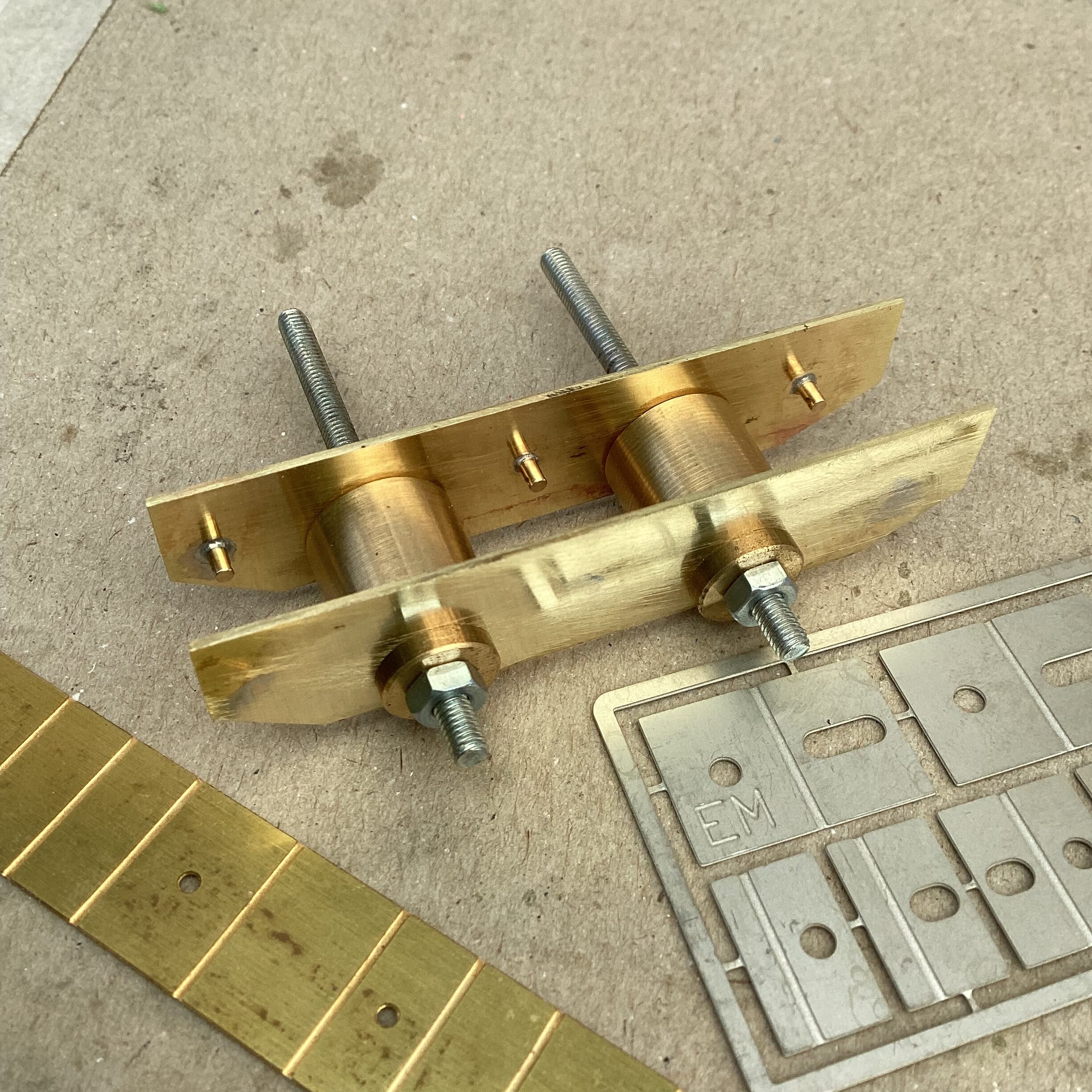
It being a long time since I’d worked in 4mm, I had to scout around for current suppliers, to see what was available, and purchased this frame assembly jig from Wizard/Comet. The “buttons” locate in the 6mm wide slots, and I used the same Comet frame spacers. I intended to follow Paul’s CSB example, so fitted some “WD” handrail knobs to support the wire.
Attachments:
-
May 31, 2023 at 5:04 pm #245150Paul TomlinsonParticipant
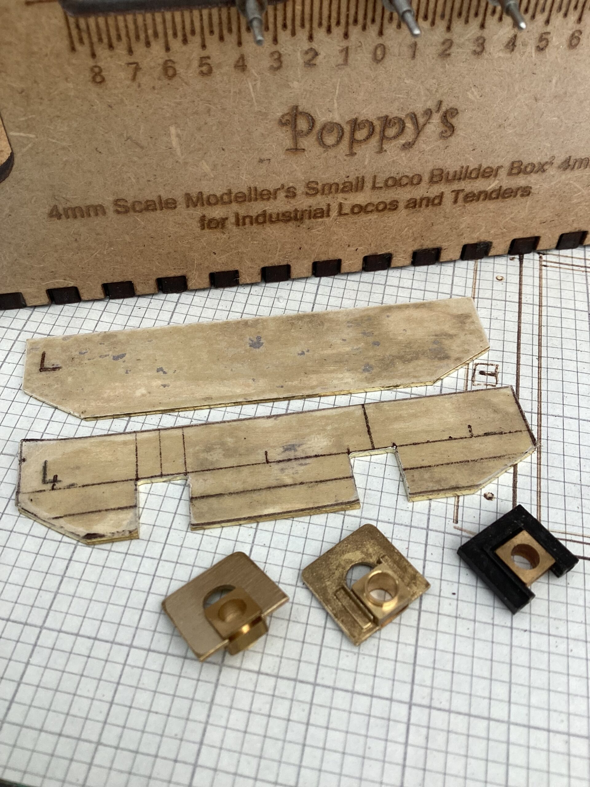
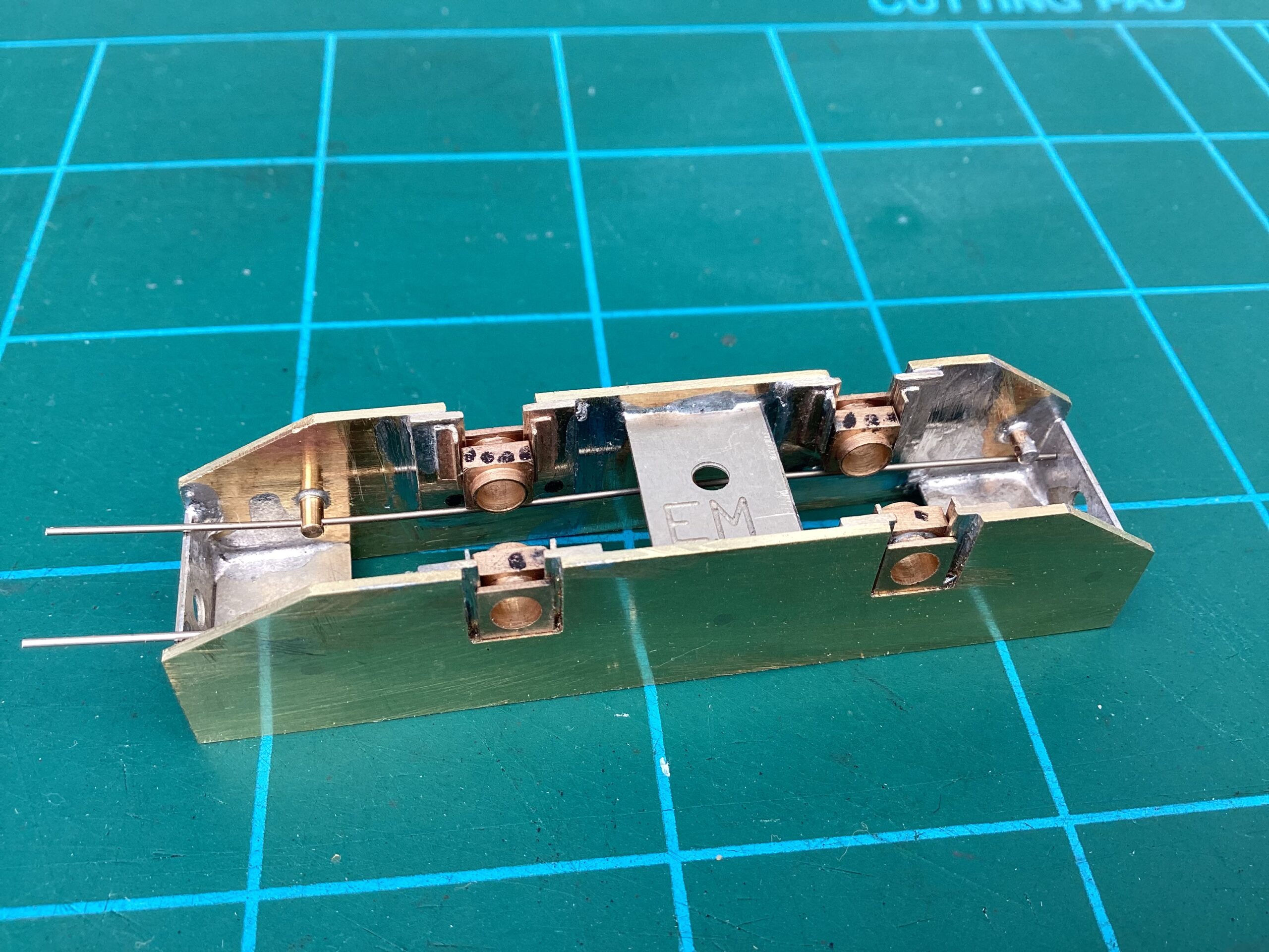
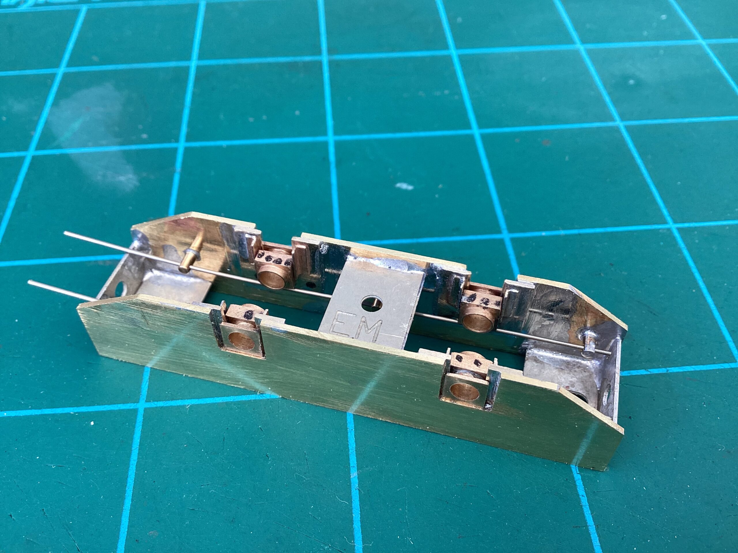
I chose hornblocks from LRM – I use a related design in 7mm, so they were familiar to me. I had a torrid time locating them accurately, and several times questioned my sanity. I used a box from Poppy’s, and some rods I’d fretted out at 26mm centres. I’ve popped a bit of n/s wire in to check the alignment – I’ve yet to solder onto the hornblocks the CSB brackets. I’m going to have to remove some of the inner bearing in order to provide room for a gearbox – I’m aiming for 7mm or so, and there’s the Slimliner Plus box from High Level (currently o.o.s.) or a slimline 51:1 one from Branchlines that’ll fit. In the meantime, I can clean up some of the messy soldering…
Attachments:
-
June 1, 2023 at 10:58 am #245157
 Stuart FirthParticipant
That looks a very tidy and solid job. I’m interested in how you attach the CSB beams to the hornblocks – Can they not just rest across the top as with your test wire?
-
June 1, 2023 at 11:35 am #245158Paul TomlinsonParticipant
Stuart, thanks very much for your interest – I’d also like to thank you for your interesting build articles in the Newsletter, esp. your adaptation of the Hornby Caley “Pug”.
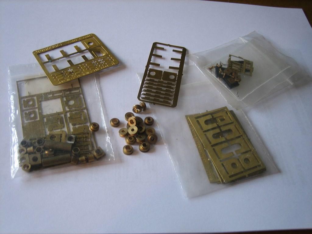
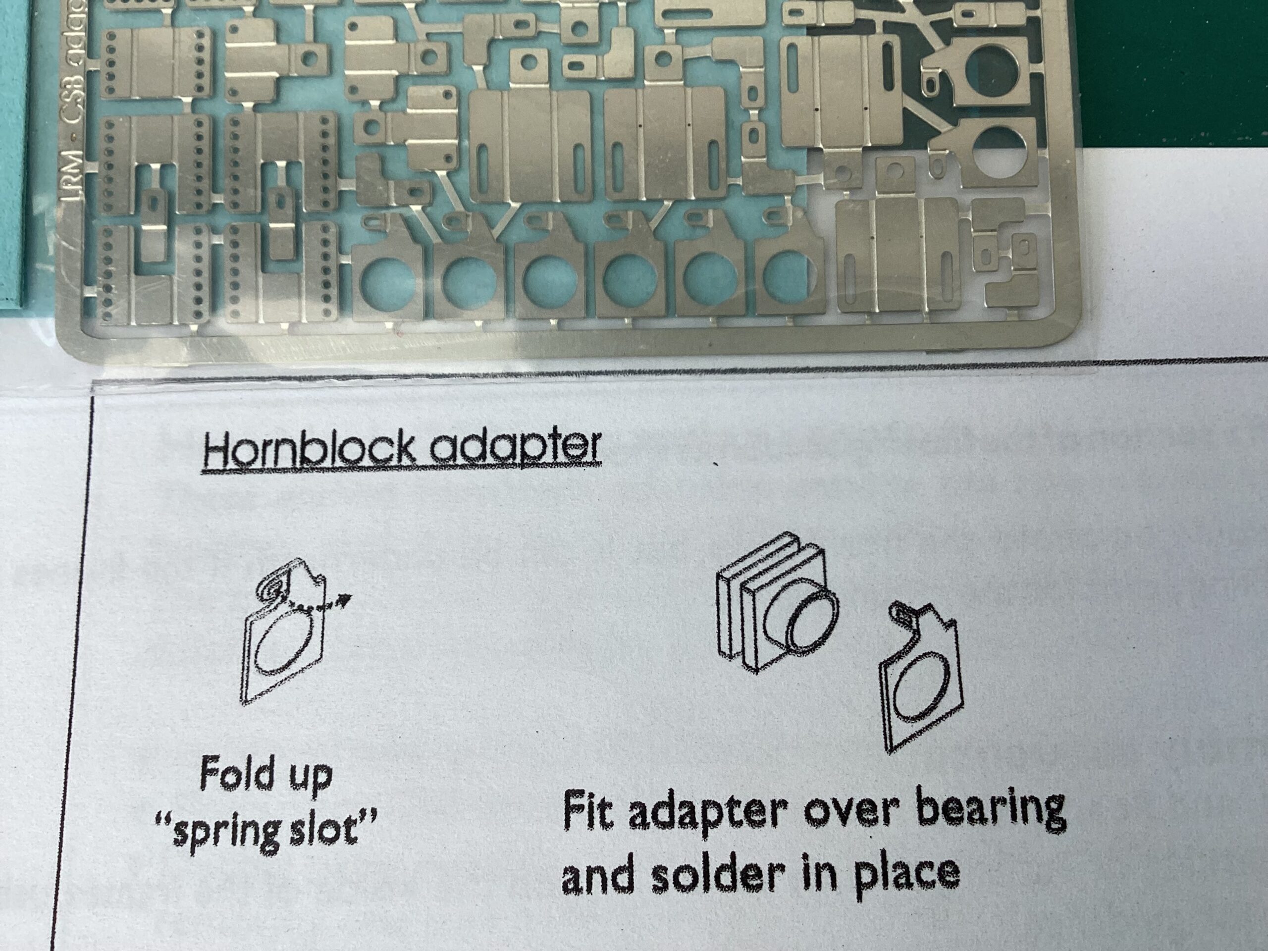
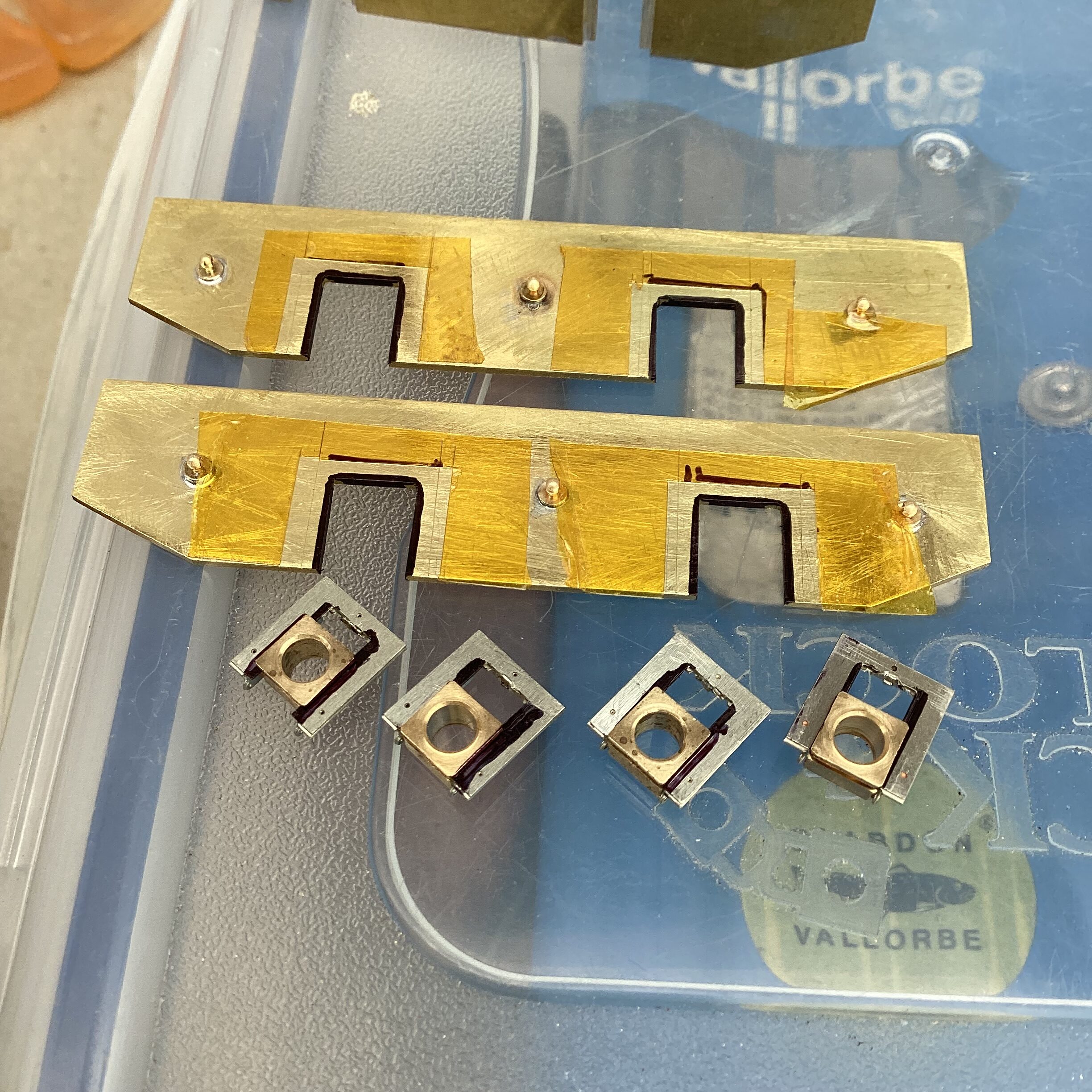
The LRM hornblocks have a circular extension, over which fits an etched bracket – a photo is worth a thousand words, so I include a shot of the instructions and fret, below. I have toyed with the idea of soldering a pivot directly to the top of the hornblock. In hindsight, it would have been far easier to leave the powered axle in a plain bearing, but I hadn’t anticipated the lack of clearance, and had fancied a stab at using CSB suspension. This is very much a learning exercise for me. Cheers.Attachments:
-
June 1, 2023 at 12:31 pm #245160Stuart FirthParticipant
Thanks for the comments. The build is very interesting. It certainly is more of a faff than compensation, but they claim it runs silky smooth, so I would like to try it in the future. Perhaps the extra slim version of the High Level hornblock is the way to go. (Picture of ropey but functional chassis attached!)
-
June 3, 2023 at 10:02 pm #245193
Paul Willis
ParticipantOn Paul Tomlinson saidThe LRM hornblocks have a circular extension, over which fits an etched bracket – a photo is worth a thousand words, so I include a shot of the instructions and fret, below. I have toyed with the idea of soldering a pivot directly to the top of the hornblock. In hindsight, it would have been far easier to leave the powered axle in a plain bearing, but I hadn’t anticipated the lack of clearance, and had fancied a stab at using CSB suspension. This is very much a learning exercise for me.
An alternative to the LRM tags are the ones from High Level. Chris has designed some very clever tags that fit over his axleboxes and allow the choice of three heights. This gives you flexibility over the height of the CSB wire over (or under) the axle centres, or within the frame profile.
https://www.highlevelkits.co.uk/product-page/csb-carrier-tag
Best,
Paul
-
June 3, 2023 at 10:23 pm #245195Paul TomlinsonParticipant
I was at Scalefour Crewe today, and among other things bought some High Level hornblocks and CSB tags. I fancy giving them a go as I think I’m making the job more difficult than it need be… anyway, I’ll have a play and post when I’ve made some progress…
The issue as I see it with resting the beam directly on the square bearing is the broad contact point – quite what the effect is, I don’t know, but I would imagine that for optimum performance, the smaller contact area the better. Just a theory…
-
-
June 3, 2023 at 10:06 pm #245194ParticipantOn Stuart Firth said
That looks a very tidy and solid job. I’m interested in how you attach the CSB beams to the hornblocks – Can they not just rest across the top as with your test wire?
You can also just rest the wire across the top of the bearing. Usually it sits in a groove milled into the bearing I believe.
This the approach followed by Dave Bradwell in his kits, although I may be misremembering as I have never had cause to build one myself. Different eras and regions as the reason for that, as I understand the kits are excellent.
Best,
Paul
-
June 4, 2023 at 10:04 pm #245206ParticipantOn Paul Tomlinson said
I was at Scalefour Crewe today, and among other things bought some High Level hornblocks and CSB tags. I fancy giving them a go as I think I’m making the job more difficult than it need be… anyway, I’ll have a play and post when I’ve made some progress…
Hi Paul,
I can understand that feeling of making things more difficult than it need be…
I’m currently coming to the end of a long build (stop-start, rather than anything else) of a GER T26 locomotive. That’s an E4, for LNER and BR types. It’s from an Alan Gibson etched kit. The kit shows its age in many ways, but it doesn’t stop it being the basis of a good model if you correct some of the more obvious errors.
In my case, I am backdating it to 1910 condition as well, so some of the extra work is entirely of my own doing.
Anyway, when it came to the tender chassis, I decided to reduce the stockpile of ageing bits in my Cupboard of Shame, and repurpose some old Perseverance hornblocks and bearings with spare handrail knobs to make improvised versions of the High Level parts:
Unfortunately, after a couple of evenings of fussing, slipped drills, soldering misalignments, and much swearing, I had a set that were complete, but nothing like as good as a set of High Level ones that I could have put together easily in 30 minutes…

So in short, don’t mess about with bodging, use the right tool for the right job…
Best,
Paul
Attachments:
-
June 4, 2023 at 10:10 pm #245208ParticipantOn Paul Tomlinson said
I was at Scalefour Crewe today, and among other things bought some High Level hornblocks and CSB tags. I fancy giving them a go as I think I’m making the job more difficult than it need be… anyway, I’ll have a play and post when I’ve made some progress…
The issue as I see it with resting the beam directly on the square bearing is the broad contact point – quite what the effect is, I don’t know, but I would imagine that for optimum performance, the smaller contact area the better. Just a theory…
I suspect that this is one of those railway modelling questions to which the answer is “in theory yes, in practice no”…
And all of this bearing (no pun intended) in mind that we are only looking at a bearing movement of +/- 0.5mm anyway. So the amount of any concave/convex flexure would be absolutely minimal.
Perhaps the biggest issue against only resting the wire on the top of the bearings is that absent any form of retention at the bottom of the hornguides (something that High Level *does* have) then your wheels would fall out of the bottom of the chassis!
Best,
paul
-
June 20, 2023 at 5:29 pm #245418Paul TomlinsonParticipant
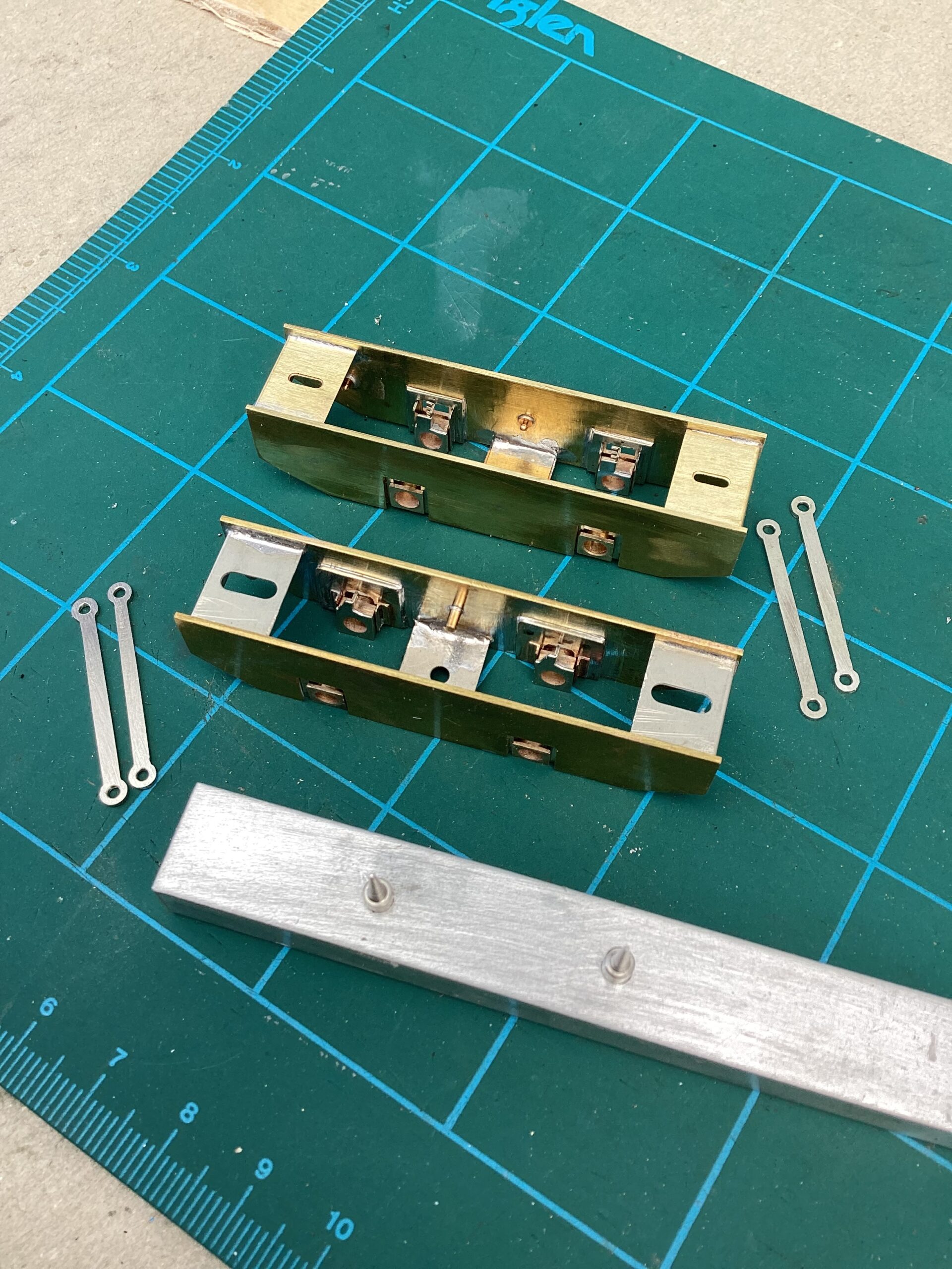
Some progress has been made, and I’ve reached another head-scratching moment… I’ve started afresh, so there’s now mk1 and mk2 frames. After I’d had chance to reflect a bit, I cleaned up mk1 to erase some of the excess solder, and applied the iron to re-seat a couple of the horncheeks so they sat truly flush with the frames. I’ve got a set of self-clamping tweezers, which helped enormously. I soldered on the csb tags to the hornblocks, and filed the inner face smooth. I’m altogether more happy with the result. I’d used a set of 7mm knobs for the csb anchors, which line up ok with the LRM tags, but as the High Level tags sit closer to the frame, I decided to set about a second chassis, along identical lines to the first, but using 4mm anchors. Not wanting to repeat the battle aligning the horncheeks, I decided to try a different approach. I’d used the vertical drill on my Unimat to drill the rods at 26mm centres, so I made a jig out of the most suitable material to hand, again using the graduated feed on the lathe bed to drill axle holes to match the rods. A bit of a gamble, but I’m hopeful for a successful outcome. After applying a bit of black marker to try and stop the solder creeping and jamming everything up, and a bit of hot tape on the frames for a similar reason, I used the jig, and the tweezers, to attach the horncheeks in the flat, then assembled the frames using the Comet jig. I thought I’d have more clearance between the hornblocks to slot the gearbox in, but both frames are pretty much identical.
-
June 20, 2023 at 5:44 pm #245423Paul TomlinsonParticipant
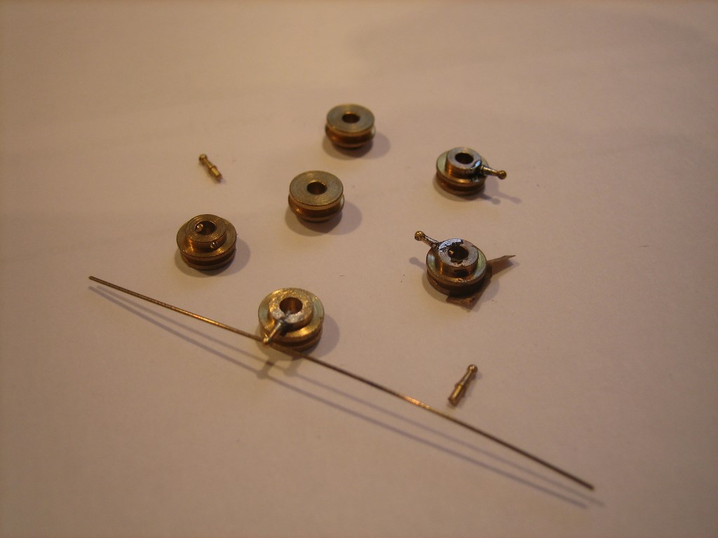
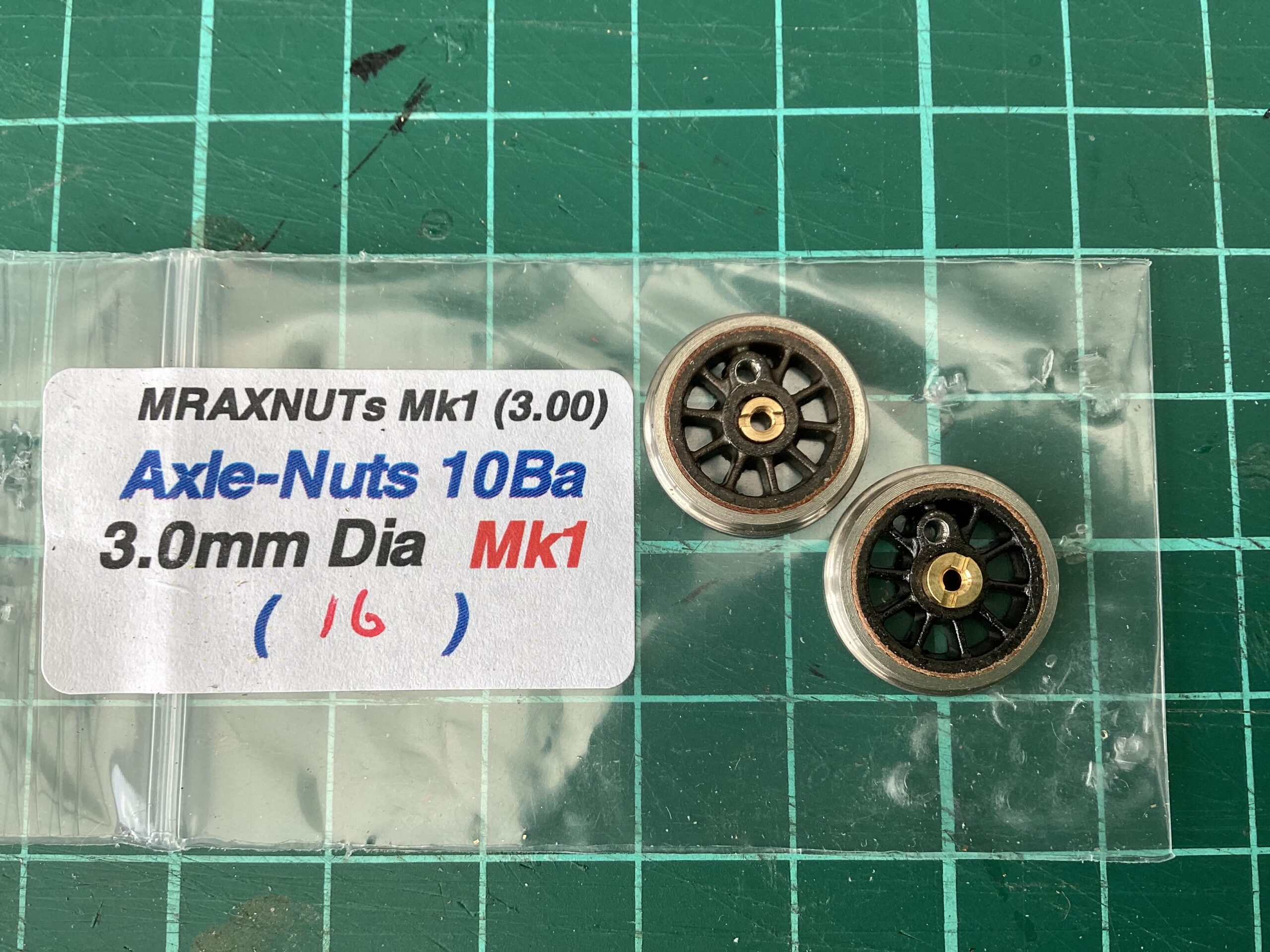
I’d hoped to have mounted the wheels before posting, so I could check that everything ran smoothly, but have hit a couple of snags with the wheels from Markits. First was the squared axle wouldn’t enter the wheel. I’m used to this, Slaters 7mm wheels typically need a bit of careful easing, removing burrs using a fine square file. So I did a bit of gentle filing, taking care to give each face in turn the same attention, until the axle end could be eased in. The second snag is when I came to add the locking nut, I found it was fractionally too large to enter the socket in the wheel – so I called it a day. I contacted Markits, who kindly sent me a set of smaller locking nuts, which easily fit within the recess. I’m not sure if these are part of their normal range, I haven’t seen any mention of them elsewhere.
-
This reply was modified 1 year, 3 months ago by
 Paul Tomlinson.
-
This reply was modified 1 year, 3 months ago by Paul Tomlinson.
Attachments:
-
This reply was modified 1 year, 3 months ago by
-
June 24, 2023 at 12:12 pm #245447Paul TomlinsonParticipant
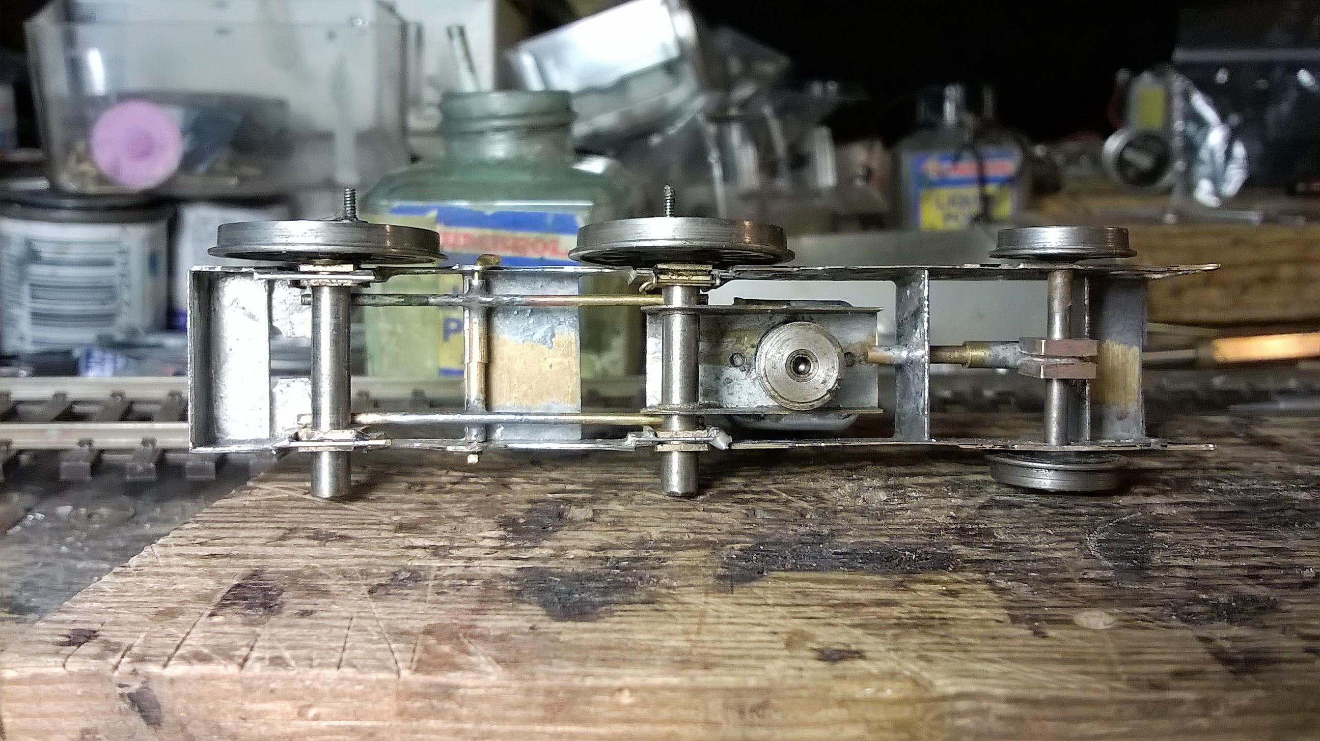
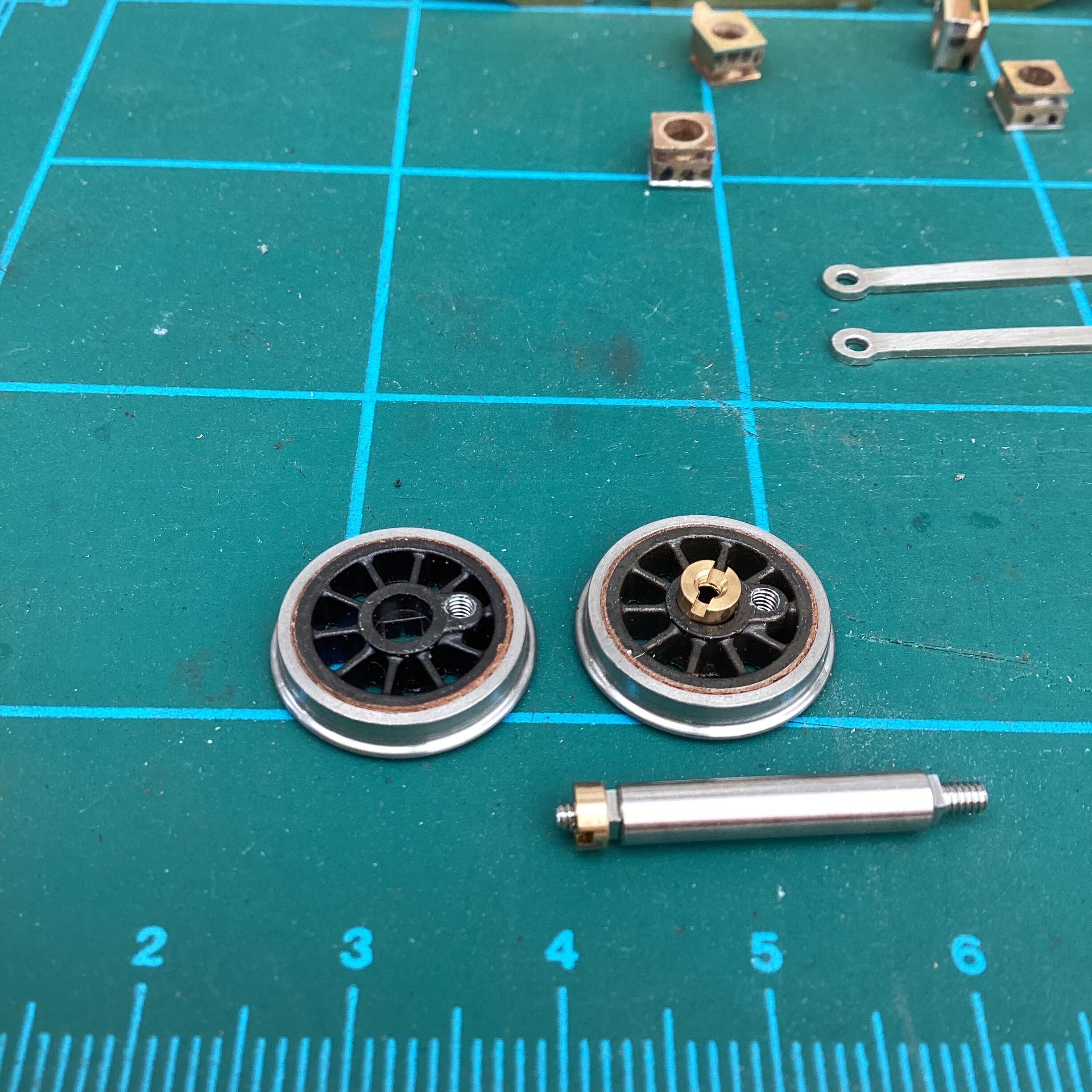
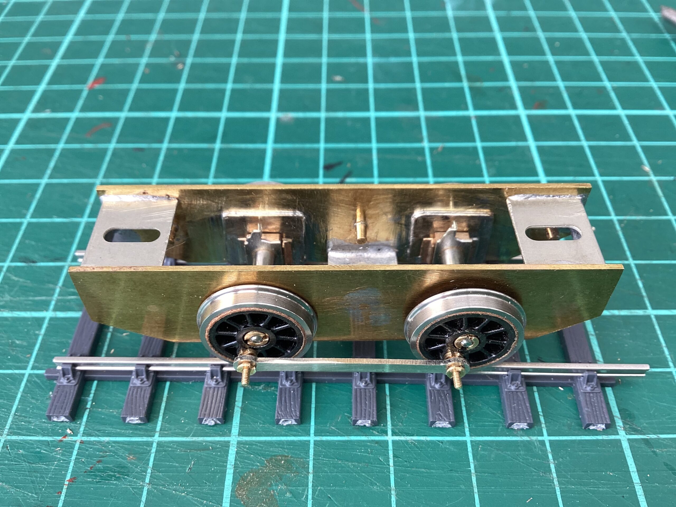
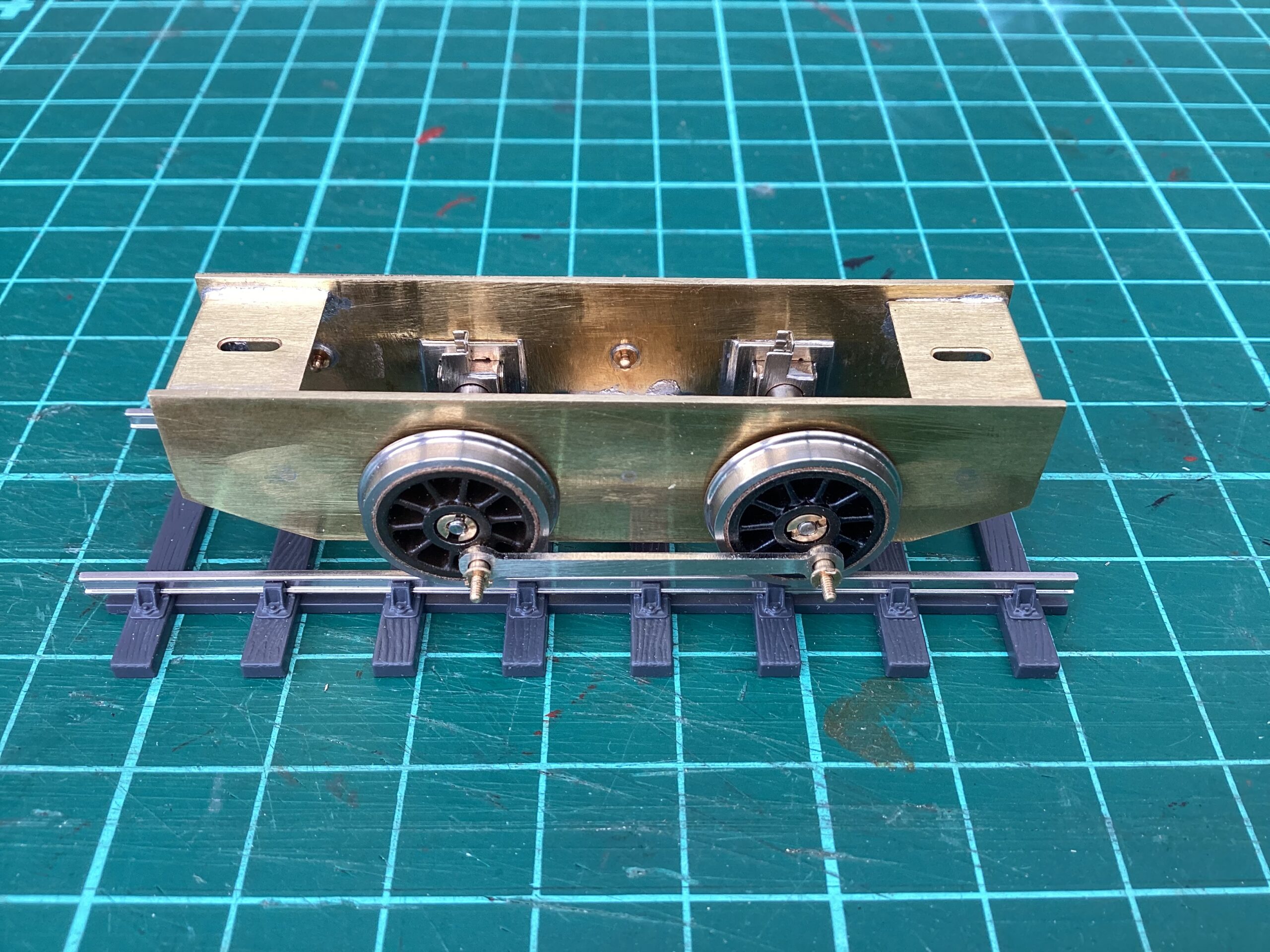
To the relief of the Chief Engineer, both run smoothly. I’m using the threaded crankpins on this build, the bushes will need filing to length.
Attachments:
-
August 20, 2023 at 6:31 pm #245890Paul TomlinsonParticipant
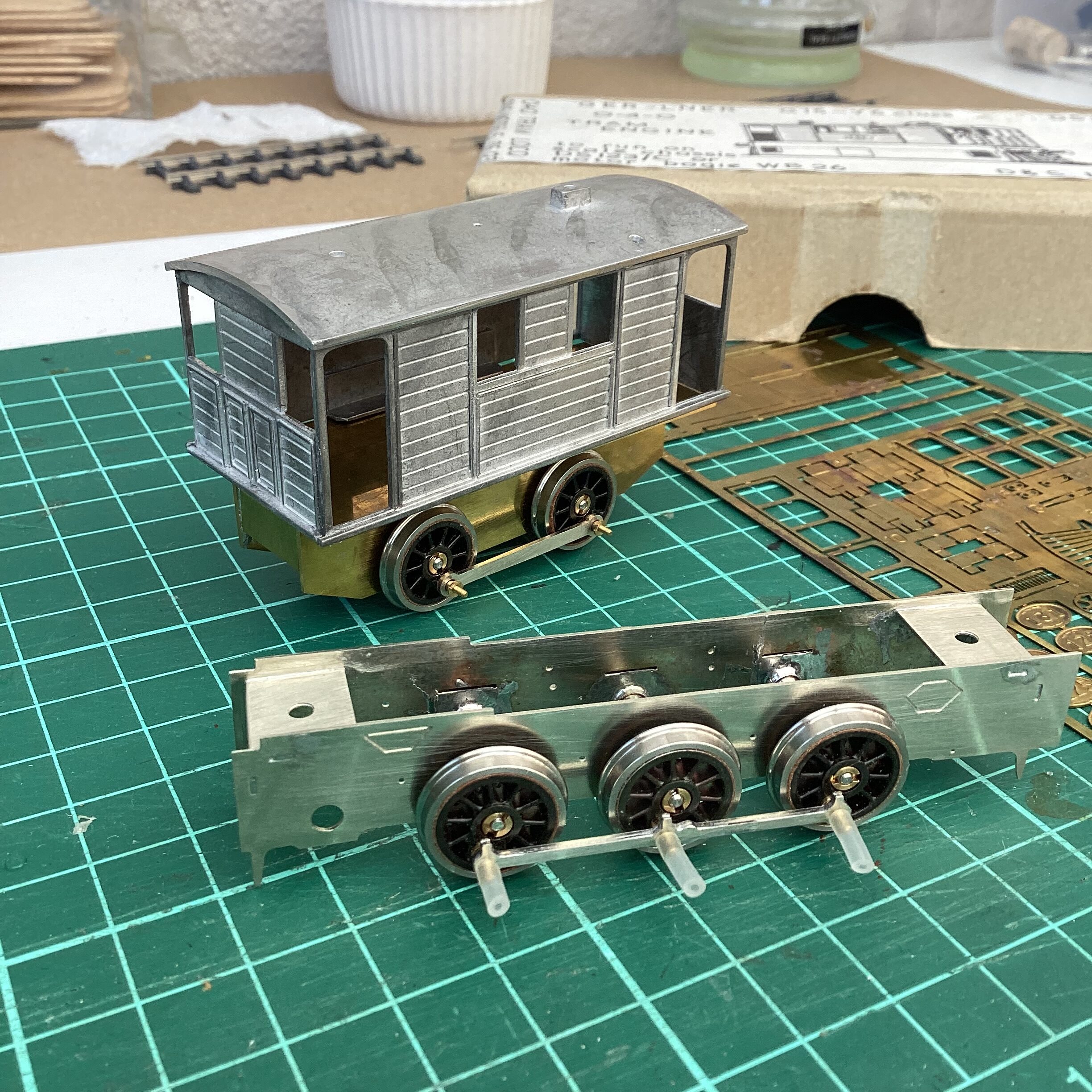
I diverted a bit and assembled a couple of Branchlines Drewry 04 chassis kits – rigid this time – and used what Markits wheels I had left to create one rolling chassis. It took me a surprising amount of time to achieve a smooth-running chassis, but I got there eventually. Over the last few days I’ve gone back to the Y6, fettling the castings (which were very good and distortion-free) and today assembling the upper body. With the castings being very fine, and probably irreplaceable, I used cyano gel to stick them together. At the moment I’ve got a shed on wheels. I have issues with the design of the lower body, so’ll be doing a bit of scratchbuilding to accommodate the scale mainframes I built.
Attachments:
-
August 21, 2023 at 2:19 pm #245895Stuart FirthParticipant
Looking good – what’s the plan for the drivetrain?
-
August 21, 2023 at 3:30 pm #245898Paul TomlinsonParticipant
Cheers, Stuart. For the Y6, I bought a High Level Slimliner at Scalefour Crewe, and one of his 1219 coreless motors. I’ve yet to decide upon the way I restrain the motor, so it allows the CSB to do it’s business. Maybe a loose loop of wire over the far end. I’ll mount a piece of copper-clad under the central spacer and try my hand at making some of the curly phosphor-bronze pickups like Paul W used on his. There’s an interesting article by Will L on the Scalefour forum about how to make them.
I also bought a couple of RoadRunners, I think, for the Drewry’s, with 1320 coreless motors. They’ll both be rigid chassis, so I’ll use a bit of double-sided tape to hold the motors in place. I’ll write that up when I get round to them.
-
-
August 21, 2023 at 10:39 pm #245916ParticipantOn Paul Tomlinson said
I also bought a couple of RoadRunners, I think, for the Drewry’s, with 1320 coreless motors. They’ll both be rigid chassis, so I’ll use a bit of double-sided tape to hold the motors in place. I’ll write that up when I get round to them.
I’ll make a suggestion here…
Rather than a bit of double sided tape, get hold of a pack of the double sided foam pads. I think they are called “Sticky Fixers” or something like that, and there are no doubt a range of generic ones.
They will allow the motor to move up and down slightly, whilst still remaining fixed. I know that you are intending to use fixed axles, but there may be a tiny fraction of eccentricity in the gearset, or in the motor, or whatever. Better to allow that tiny bit of flex to take place, rather than binding or rattling.
I do try and avoid rigid motor mounts wherever possible. The ways that I do this will vary depending on the application: foam pad, blutac, even just rigid wires. Anything that gives a small amount of movement will help, in my experience.
Best,
Paul
-
August 22, 2023 at 8:46 am #245919Paul TomlinsonParticipant
Cheers, Paul, noted…
-
This reply was modified 1 year, 1 month ago by Paul Tomlinson.
-
This reply was modified 1 year, 1 month ago by
-
-
August 22, 2023 at 9:23 am #245921
Bob Allison
ParticipantPaul T,
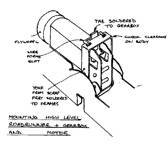
Have you seen this solution by Dave Bradwell, taken from the Scalefour Forum?
-
August 22, 2023 at 10:38 am #245922Paul TomlinsonParticipant
Thanks, Bob, I hadn’t seen it – looks like he’s designed the mount to allow the box to move vertically, but prevented from rotating by the tab-and-slot. Food for thought…
-
-
August 22, 2023 at 7:40 pm #245931Participant
Exactly so, Paul. The driven axle must be allowed to move vertically and tilt sideways, or the springing is ineffective.
Dave B has a reputation for coming up with straightforward, well engineered solutions, so you can be sure that anything he recommends will work properly.
Bob
-
-
AuthorPosts

- Only logged in EMGS members can reply to this topic