› Members Forum › Automation › Electronics › Van Rides
Tagged: automation, electronic kits
- This topic has 0 replies, 1 voice, and was last updated 2 years, 2 months ago by
Geoff Latham.
-
AuthorPosts
-
-
February 27, 2024 at 8:00 pm #248131
Geoff Latham
ParticipantVan Rides
The photograph shows a trial board for the electronics of a fully automated proposed layout tidied up to form part of a MERG display. It uses Peco N gauge track and aptly named MERG Pocket Money Projects (now gradually being replaced by Pocket Money Kits using a printed circuit board instead of the stripboard shown).
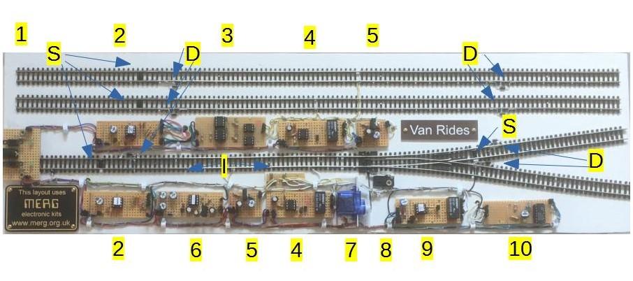 The representation is of a section of a single main line and passing loop on the upper two parallel tracks with a local train stopped at an off-scene platform when necessary. A loco and brake van alternately traverse each leg of the Y track giving van rides from a supposed cattle dock at “I”. The end stop sections would be hidden.
The basis of operations are simple shuttles with modifications to suit the scenarios using the following components and methods:
S TCRT5000 infrared sensors
D track breaks bridged by diodes
I track breaks forming an isolated section
1 power input socket for 12vdc switched mode supply with switches and indicator LEDs. For a 16vac supply PMP6 (not shown) could be used to provide 12vdc.
5 PMK10 is a 12v speed controller that can be used with the supplied potentiometer, or a preset trimmer as shown, to provide an adjustable constant speed.
4 PMP4 is a simple shuttle that uses a timer to trigger a double pole double throw relay at regular intervals to reverse the track polarity. The diodes halt the train until the current reverses.
2 PMP4a shuttle add-on alternately outputs 5v or 0v to operate a turnout linking adjacent tracks when sensors in both tracks are activated (covered) allowing trains on the tracks to run alternately.
For the Y track a single sensor is placed at the tail end and connected to both inputs thus triggering every time it is covered, so a single train can traverse each fork alternately.
3 A bespoke board using two op-amps and two opto-isolators. The op-amps are wired as a positive and a negative voltage comparator, so the 5v or 0v input from board 2 will always produce a positive output to one of the opto-isolators. One of the track feeds from the shuttle is fed to the corresponding rail of each track, the other to the second input of the opto-isolators, the outputs of which are connected to the other two rails. At any one time three of the rails are of similar polarity and thus only one train will run resulting in the two trains travelling out and back alternately.
6 PMP18 EzyPoints servo module converts the input from 2 to signals for changing the position of a servo and enables adjustment of the end points and speed of throw.
7 servo motor connected to turnout tiebar.
8 microswitch to change turnout frog polarity.
9 PMK15 train auto stop has two selectable modes using one or two sensors to stop a train anywhere or at two positions such as at either end of a platform on a single track shuttle. Shuttle mode is needed because the train passes in both directions. One stop is required every fourth journey, achieved by placing the sensor in one leg of the Y before the track break. Triggered on the outward journey the isolated section is dead but with nothing in it, triggered on the inward journey from that leg only, the section is dead when the train arrives.
10 A bespoke board. The output from the spare sensor from PMP4a is insufficient to operate PMK15 but using one channel of an LM324N quad op-amp wired as a comparator and a 10k preset trimmer producing 0V when just triggered, the 5v or 0v output is.
Apologies for the quality of the image – the original photo was probably not the best, finding an application for annotation was difficult (used LibreOffice Draw) and uploading was a nightmare -I had not looked far enough down the Export as options to find JPEG.
I hope the details are of use in showing the possibilities for simple automation using and modifying inexpensive kits.
Geoff Latham
-
-
AuthorPosts
- Only logged in EMGS members can reply to this topic