› Members Forum › Scratch Building › Locos › LNER F5 flexichas
- This topic has 7 replies, 3 voices, and was last updated 4 years, 1 month ago by
 Nigel Burbidge.
-
AuthorPosts
-
-
June 6, 2022 at 8:06 pm #241729
 Nigel BurbidgeParticipant
Many years ago I built an Alan Gibson F5 for my old branch terminus layout. It worked well and I was content with it until I started building Elmham Market. By this time the Gibson sprung hornblocks were getting rather tired, it didn’t like the tighter curves I squeezed into Elmham Market and I wasn’t sure what to do with it. I saw Nick Ridgeway demonstrate his F4 at ExpoEM a few weeks ago and determined that I should follow his example and go flexichas. I toured the exhibition hall with a purpose and bought some nickel silver sheet, EM frame spacers, suitable Gibson wheels and some LRM flexichas hornblocks (enough for two chassis as I have an unbuilt F6 and figured I might get some savings in effort if I built two at once). I then spent several evenings reading and re-reading Mike Sharman’s excellent book on flexichas principles.
The 2-4-2 wheel arrangement is quite complicated to arrange in flexichas format as, effectively one has to create a mini inner frame to pivot the driving axle off. That gives two pairs of axles (one driver and one pony in each pair), with the driving axle moving up and down but not pivoting.
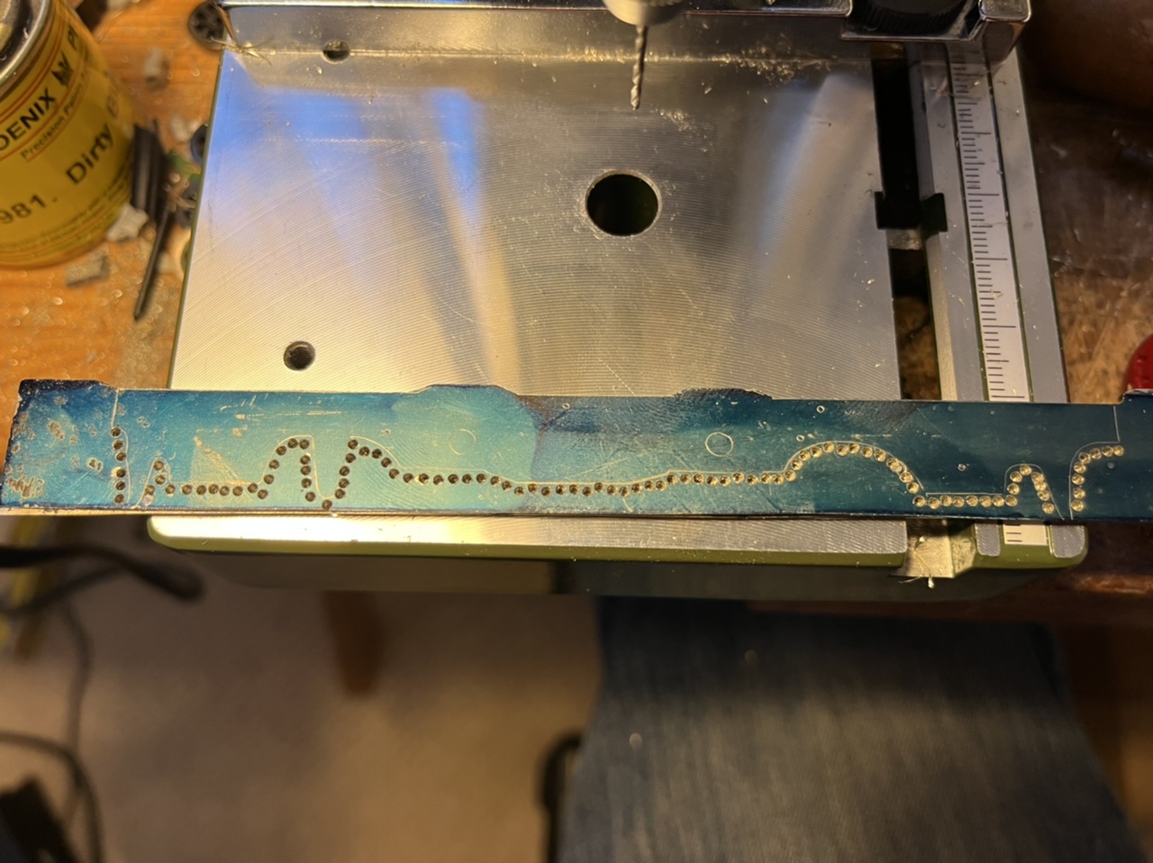
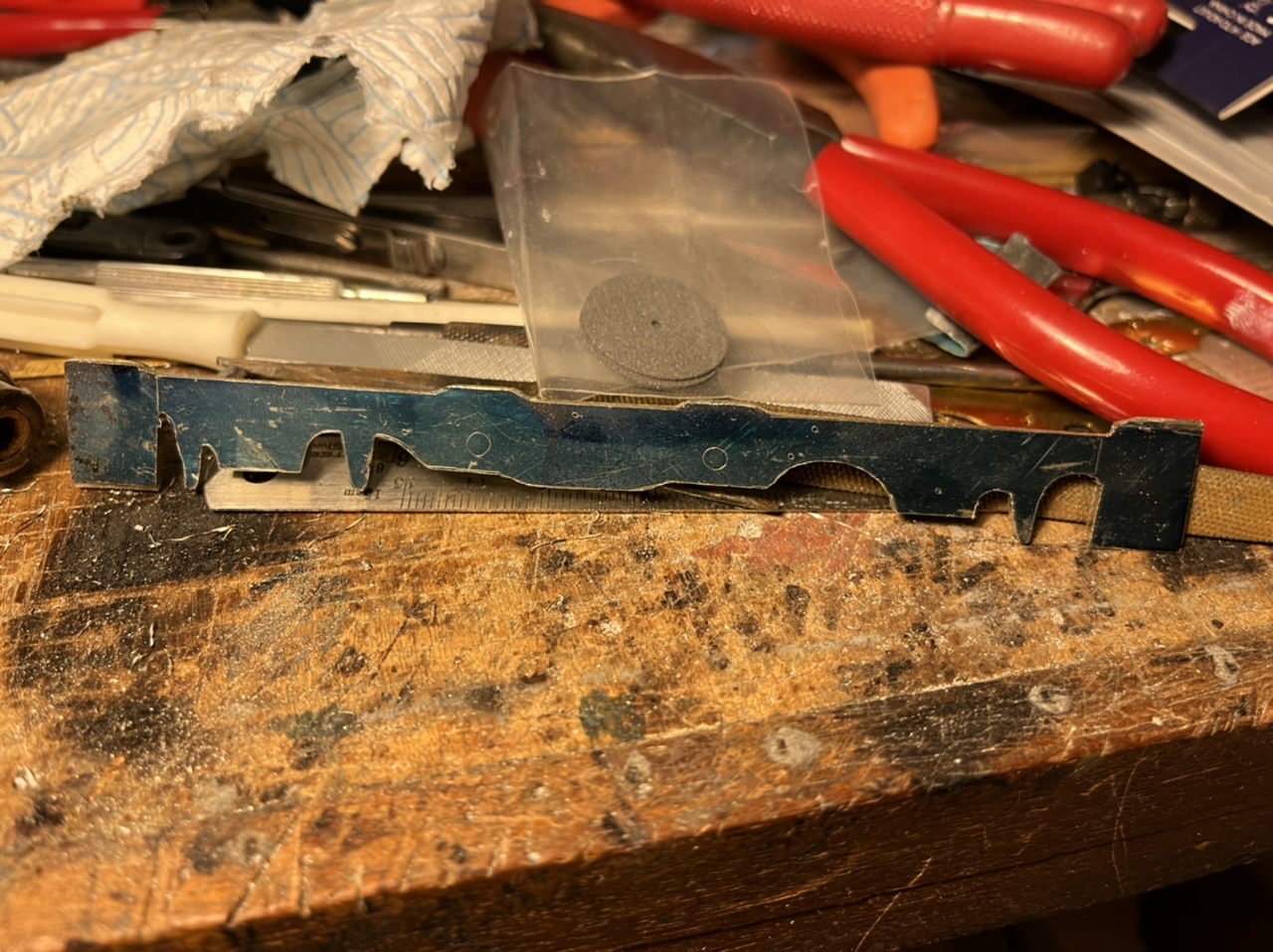
I cut out four blanks from the nickel silver sheet and soldered them together then blued the top sheet and marked out the outline. It was then an evening’s cutting (helped by chain drilling the more curvaceous bottom outline) and filing to the finished shape. Holes for the brake hangerd and pivot points for the compensation beams were also cut out.
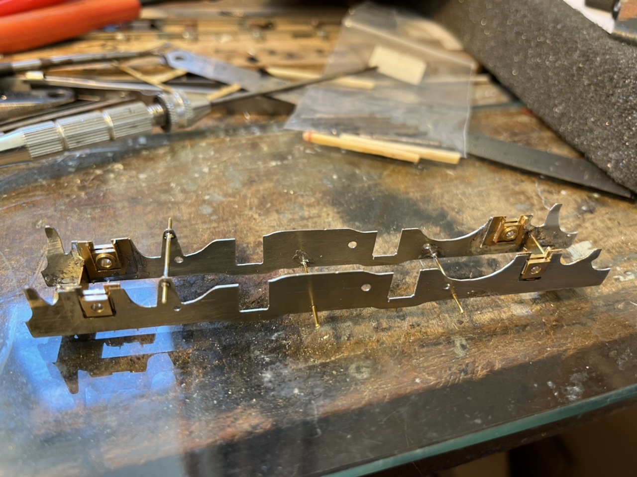
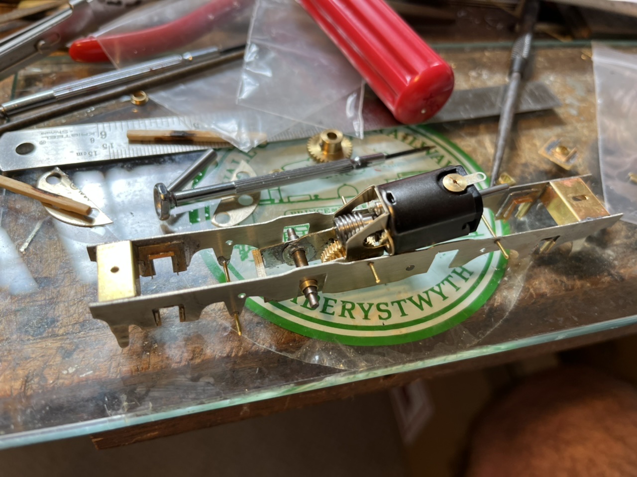
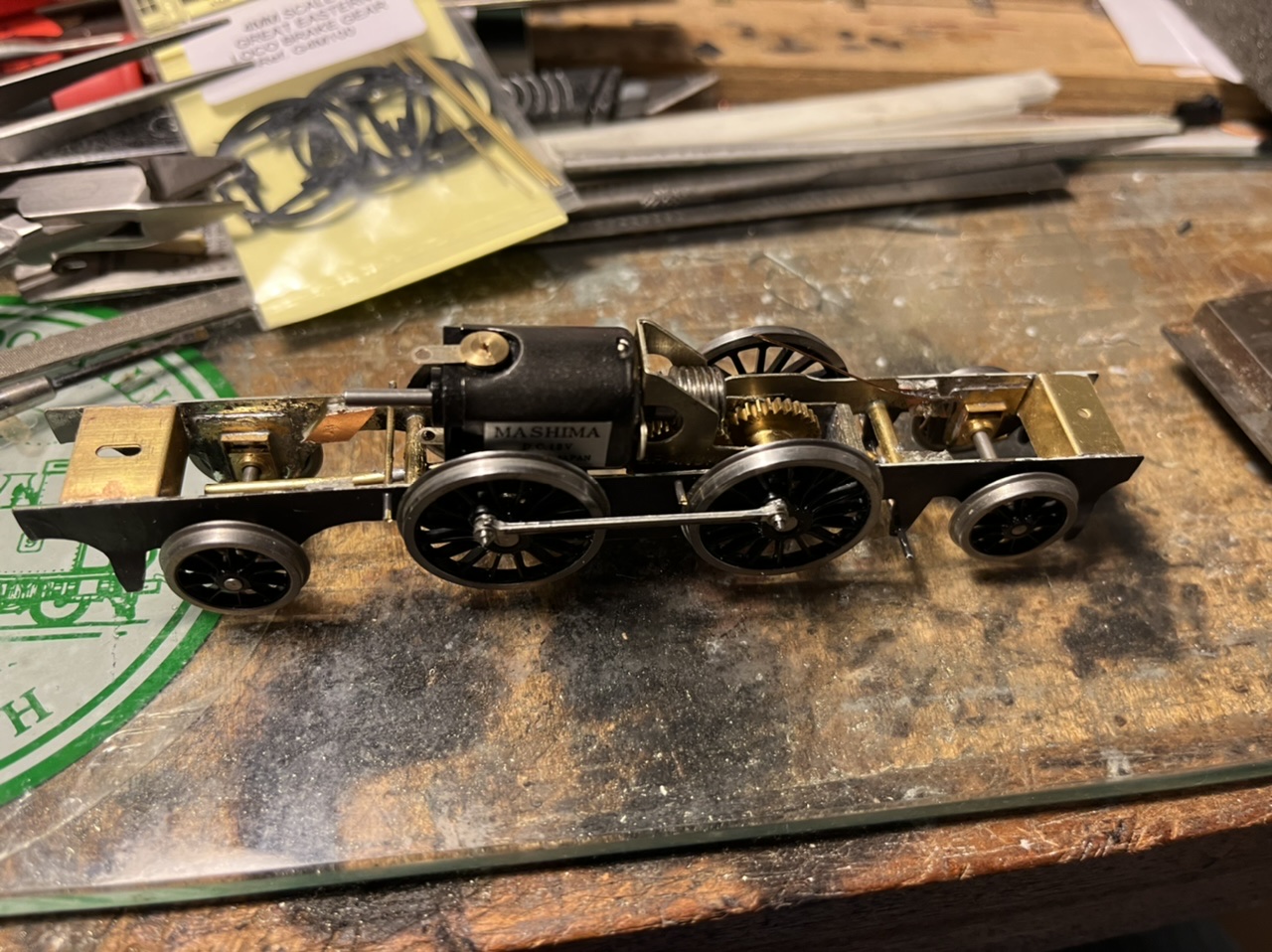
Out came my trusty sheet of plate glass and the frame spacers were soldered on, and 0.9mm wire soldered in to form brake hangers. Next was the mini chassis. This was cut out using more of the nickel silver sheet and was made quite robust as I had some 2mm steel bar in stock and 2mm inside diameter brass tube. One end of the mini frame sides was drilled to accept the brass tube (3mm outside diameter) and the other end drilled 4mm to accept the LRM top hat bearings. A robust end of nickel silver was also soldered on to make a firm frame. I then built up a Branchlines multibox, attached a Mashima 14/20 and fitted them to the mini inner frame. The whole arrangement was soldered into the frames and primed and painted. That is the current state of progress and the photos attached hopefully show better than I have described how it goes together. I haven’t finished yet but if there is any interest will give updates as I go along.
-
June 7, 2022 at 12:21 pm #241738
 Stuart FirthParticipant
Nigel those frames look superb. Interesting that you used the LRM hornblocks as I’ve got some to use in a future project. They certainly assemble more easily than the MJT type I normally use. To achieve that chain-drilling you must have better drill bits than me – it would take me a year to drill all those holes! A piercing saw with very fine blades, such as 5/0 would be my usual tool for such a job, though I inevitably break a few blades every session.
Look forward to updates.
-
June 7, 2022 at 12:40 pm #241739Nigel BurbidgeParticipant
Thanks Stuart! I do have a pillar drill and that made the chain drilling much easier. I must also invest in a piercing saw, especially if I am going to make a habit of this. Bit of a one step back and two forwards last night. Having soldered the hornblocks in and added the wheels, I found I must have mis-measured somewhere as the loco was sitting too high on the frames. A matter of unsoldering, filing deeper recesses in the frames, refettling the hornblocks and resoldering. Second go was OK. I then spent the rest of the evening shaping the compensation beams and testing them for height and vertical movement in the axle bearings. I’ll take a couple more photos of progress this evening and post them up.
-
June 7, 2022 at 11:26 pm #241742Nigel BurbidgeParticipant
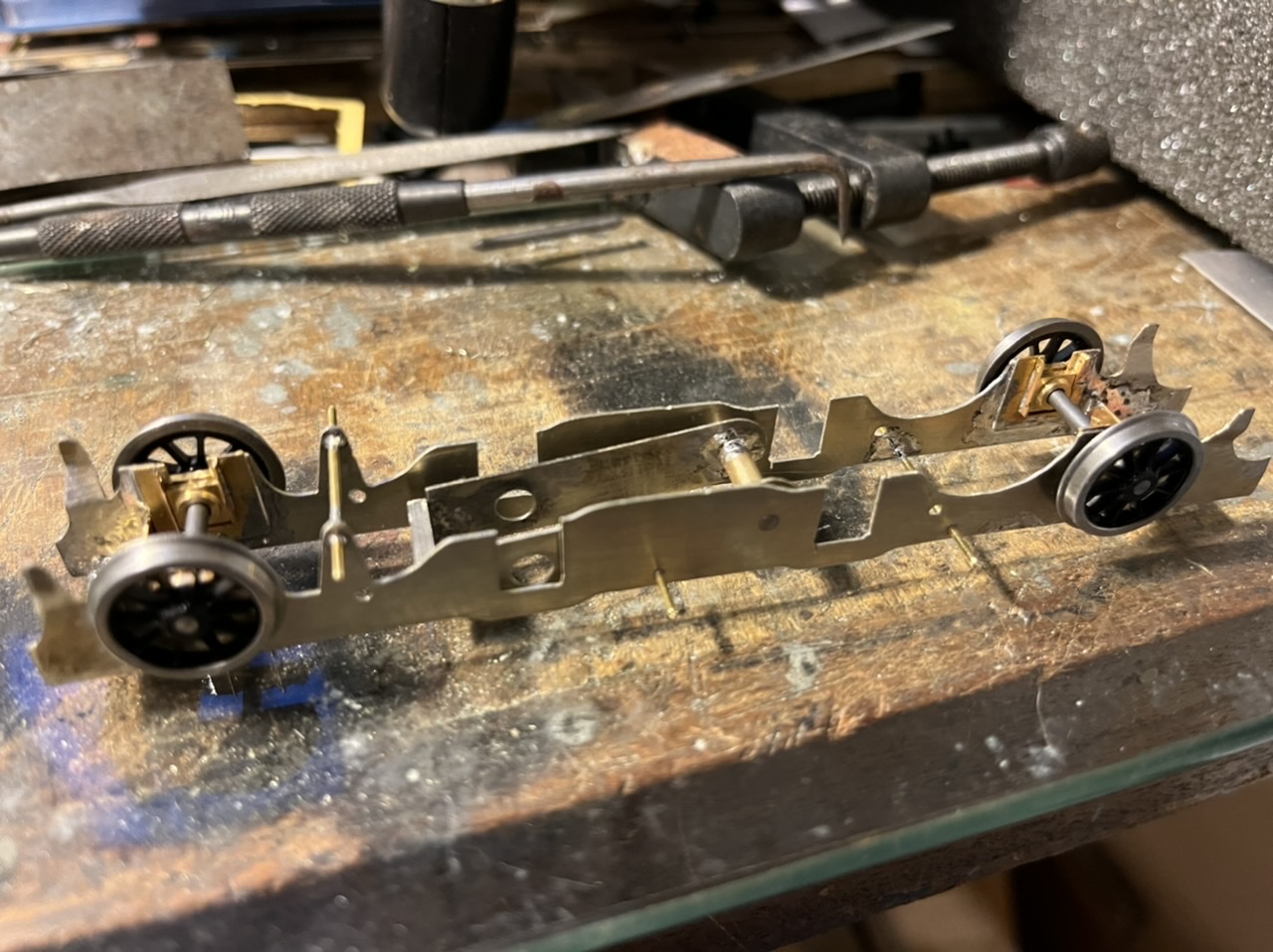
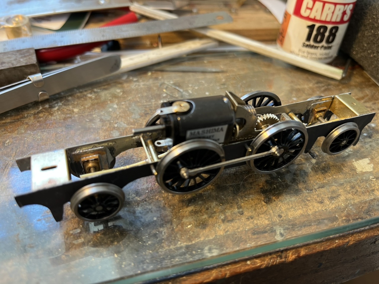
So good progress (despite spending much of the evening going out for supper with friends). Beams soldered in and the chassis seems to run quite freely, although I think I will open out the coupling rods a bit more to make sure. Attached are a few photos of progress since the last shots.
-
June 8, 2022 at 12:54 pm #241747
 Trade OfficerKeymaster
Hi Nigel
Just picked up on this thread.
Some nice work there. I have a 4-4-0 director class that I built from a little engines kit many years ago. It has a rigid chassis is not a very good runner – derailments etc. I am probably going to need to build a new chassis so I will interested in following your build and seeing your thoughts on the use of the flex has I approach. I have been reading the Mike Sherman book. Quite a detailed study
John
-
-
June 8, 2022 at 8:32 am #241746Stuart FirthParticipant
Nice !
What kind of curve can it handle with those leading and trailing axles running in proper bearings? Is there much sideplay? I have a LNWR Coal Tank to build and can’t decide whether to do it this way or to fudge it with some sort of ‘pony’ truck. Mind you Saltport has some nasty curves.
-
June 8, 2022 at 3:22 pm #241750Stuart FirthParticipant
I invariably use compensation – it actually seems easier to me to use the rods to set up the wheelbase so that you know it’s right. Then if a chassis runs roughly or a little tight you know what the problem isn’t !
John – in his chassis building book, Iain Rice tackles some tricky ones like 4-4-0’s. It’s an old book of course and the information on motors and transmissions is very out of date, but the basic chassis building advice is pure gold. Of course many of the P4 folks have moved over to CSBs now – (“Compensation ? That’s so last week !”) but I see no reason to change.
-
June 8, 2022 at 11:27 pm #241757Nigel BurbidgeParticipant
Thank you both for your kind comments. I have spent an enjoyable evening tweaking and adjusting the pony truck hornblocks and the compensating beam at the front end. I put the body on and pushed it around the tightest curves on the layout (about 3’) and first time one end didn’t want to play, hence the adjustments. I also slackened the coupling rod holes at the same time.
After those adjustments I pushed the loco, with body on, around the whole layout and it was very free wheeling and happy with the curves on offer. I’m not sure it would go round anything much tighter than 3’, so probably not ideal for industrial locations with tight curves.
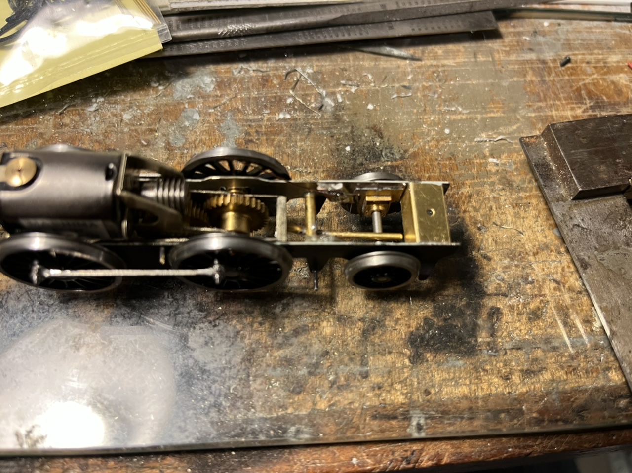
I then had the bright idea of testing the gearbox (why didn’t I do that before I ask with the benefit of hindsight?!). The intermediate gears were pretty much locked solid so some careful lubrication and gently prising of the gears got it freed up. I am now fitting the pick ups, which requires some imagination because the mini frames holding the driving axle and gearbox takes up the space where I would usually glue some copper clad paxolin. The photos show progress so far.
John, I have a PDK Claud Hamilton to build and will definitely try flexichas on it. Mike Sharman recommended combining that with a hidden bogie holding the front two axles of the tender, then weighting the tender and using that weight to bear down on the rear of the engine to transfer some more weight onto it and increase hauling capacity. I will definitely give that a go.
-
-
AuthorPosts
- Only logged in EMGS members can reply to this topic