› Members Forum › RTR Conversions › Locos › Converting a Hornby Peckett B2
- This topic has 18 replies, 6 voices, and was last updated 2 years, 8 months ago by
Giles Favell.
-
AuthorPosts
-
-
January 14, 2021 at 7:55 pm #240736
Richard Spratt
ParticipantFor my first RTR EM conversion I’m going to convert my B2 which is currently on the workbench being converted to a B1 with dcc sound. The axles are 1.9mm diameter. Do I just need some longer axles and spacer washers? If so where do I order them? The current axles appear to be knurled for the drive gear and I assume the wheels. How do I achieve a tight fit on unknurled axles?
-
January 15, 2021 at 12:37 pm #241092Participant
Ok having slept on it I have remeasured. The axles are 2mm x 20mm. So I’m looking for 2mm x 22.3mm as the current bb is 14.2mm.
-
January 20, 2021 at 12:48 pm #241093
 Trade OfficerKeymaster
Hi Richard
Unfortunately I am awaiting 2mm EM axles to be manufactured. In the current climate that is probably quite a few weeks away. I have had a look at a few retailers and they only seem to sell axles with their wheel packs
I do have some 2mm EM axles in my personal odds and ends box that came out of some Alan Gibson wheel packs (You get plain and pinpoint and I used the pinpoint). You are more than welcome to them.
The alternative is to cut down some pinpoint axles
As for washers the stores have a fair range in different thicknessesThere are probably 2 ways to fix the drive gear ;
1. Use something like loctite bearing fix
2. Roll the axle along a flat surface with the side of a file (the one that has teeth) where the gear sits. Press down fairly hard which should produce a similar knurled effect. BUT test on a sacrificial axle firstJohn
-
January 20, 2021 at 3:06 pm #241094Trade OfficerKeymaster
The suitability of the wheels depend on what the tread profile is like. Most modern RTR can be used by just pulling them out or replacing the axle
-
January 20, 2021 at 8:24 pm #241095Participant
John, I have plenty of axles thanks, but not ones with knurled ends. I’ll try using your file method in the middle of an axle where the drive gear goes.
Thanks
Richard -
September 8, 2023 at 6:03 pm #246284
Giles Favell
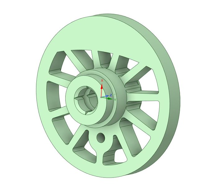
ParticipantI’m having a think about converting my B2, and with the wonders on 3D printing, I am printing new wheel centres, with finer tyres. I think the fi ished wheelsets will just sneak in between the existing slide bars, but we will see…
It occurred to me that I can print new wheel centres with extended muffs so as to reuse the existing axles. The advantage is of course the centre axle with the final drive gear which can remain undisturbed. We will seehow well this works. I will use Devcon mixed with talcum powder for the adhesive, and I’ve left channels for it to fill. This mix sets nice and solid.
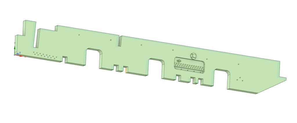
I shall also print new dummy side frames to slip over the existing cast ones. This should help the appearance, rather than leaving a gap. It remains to be seen how well I’ve measured everything! I expect so e re-prints will be called for. If this works, it will make for a relatively easy conversion to EM. P4 may need the cylinders and slide bars moving out a tad…. we will see

-
September 10, 2023 at 4:49 pm #246295
Bob Allison
ParticipantGiles,
I have a feeling that 3D printing is the future of wheel production, so I hope you’ll keep us posted with progress. Solid ballast weights of the right thickness and profile for individual locos, flexibility to match existing axles, perhaps grooves moulded into the hub and the back of spokes to facilitate split chassis construction, the list of benefits goes on.
Just out of curiosity, how do you plan to fix the tyres to the hubs to ensure concentricity?
Bob
-
September 10, 2023 at 5:58 pm #246296Participant
Hi Bob,
The wheel centres have printed rather well (a far cry from even a couple of years ago….), printed in ABS like resin at 10 micron layer height, and the accuracy is pretty good. They are 0.05mm over in diameter, and have been pressed into the tyre, with a gentle punching around the edge to get the final seating. I don’t think they will go anywhere. The axles are pressed in using two filament printed jigs – one to hold the wheel centrally and flat, and the other to hold the axle centrally and square. A small blob of Devcon/talcum powder mix was put into the wheel hole before pressing. Ive done two wheels thus far, and they’ve come out nice and true (and solid, now the adhesive mix has gone off!).
I’ve managed to reuse Hornby ‘s very nice threaded inserts in the crank pins which will make a nice neat job. These are inserted into a counter-bored hole from the back, and again retained with a Devcon/Talc mix.

The frame overlays have been printed and fitted with remarkably little adjustment.


Importantly, it looks like they will do the job without causing any unwanted issues. It’s necessary to file away all the existing surface detail before fitting, but that’s a small job.
-
September 10, 2023 at 6:01 pm #246297Trade OfficerKeymaster
Giles
I have done a few experiments with 3D printed wheels on my filament 3D printer – a relatively low end Creality. It was part of a trial that the Board wanted to look at to get relatively low cost alternative supply of wheels. The main problem was getting the tyre and wheel manufactured separately and hope they married up and then getting them assembled.
Are you using a resin or a filament printer? The initial problems i had was with getting the printer set up correctly so that the wheel was within tolerance and concentric. What CAD software?
I have to admit that I turned my own wheels on my lathe (I’m afraid I am a bit of tool freak🙄) I eventually got a decent 3D print that fitted the tyre with no concentricity issues. It was trial and error though
The material I used probably wasn’t strong enough (PLA) for a driver but is probably OK for wagon wheels etc
I would be interested in your progress as I didn’t really get any further than a few prototypes and you have inspired me to have another go
Bob
You are right about 3D printing fundamentally changing our hobby. With wheels the trick will be marrying the tyre to the centre. Unless somewhere out there is a metallic resin or filament to print the whole wheel. I remember a couple of years back reading on a forum about someone who was trying to print their own track – including the rails!
John
-
September 10, 2023 at 6:29 pm #246298Participant
I use a resin printer for the modelling, and a filament printer for making jigs and tooling etc….. I have a Mars 2 Pro, which is elderly by now, but produces extraordinary work. The body of the 0-14 loco is entirely printed, even with lamp brackets in situ.

I use Designspark Mechanical from RS for the drawing side, which has a free version – long may that continue…
I find that home 3D printing can certainly match commercial standards aesthetically, although not fully in materials, and is a wonderful ‘extra’ tool in our armoury. I can draw and print stuff to a greater accuracy than I can any other way. I hope it never replaces traditional building, but it certainly complements it.
-
This reply was modified 2 years, 8 months ago by
-
This reply was modified 2 years, 8 months ago by
-
September 11, 2023 at 10:54 am #246305Participant
Inspirational, in the literal sense of the word!
Bob
-
September 11, 2023 at 10:58 am #246306Trade OfficerKeymaster
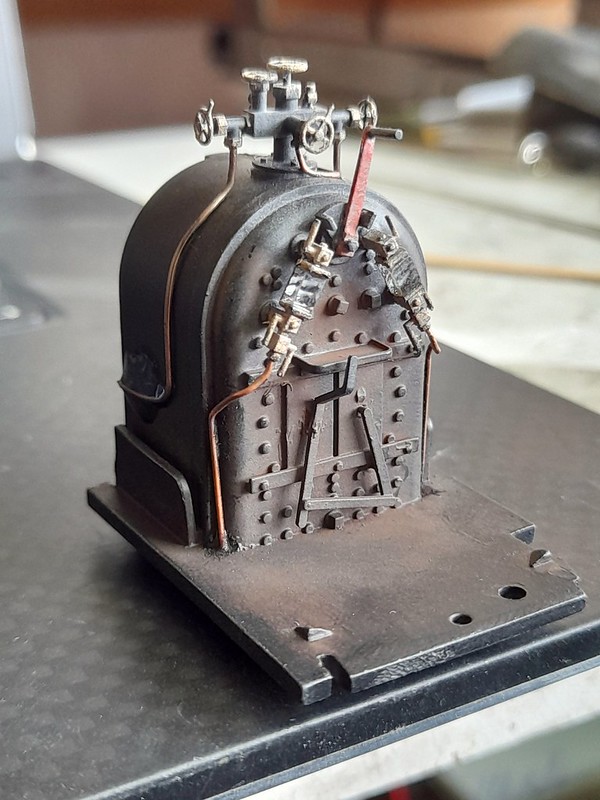
That firebox looks good. Was there much clean up to do as the details is really crisp even in closeup!
John
-
September 11, 2023 at 12:08 pm #246307Participant
Thank you!
No – No cleaning up at all, other than the sprues themselves. As an example, this is the tank /boiler straight off the build plate

And this is the safety-valve from an 0-14 Kerr Stuart Tattoo which it wouldn’t be possible to clean up!

-
September 12, 2023 at 2:36 pm #246336Participant
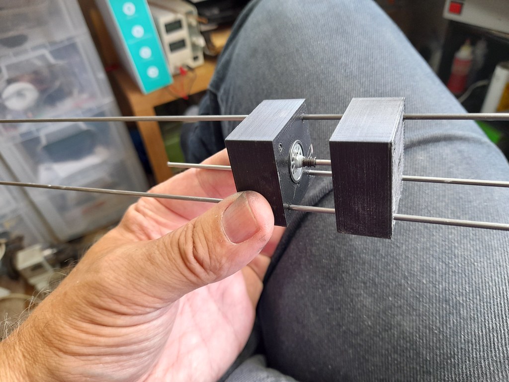
I used a pair of printed die blocks to press the wheels onto the axles whilst at the same time quartering them. When the chassis had its rods fitted, the quartering appears to be fine…..
Unfortunately it turned out I did need to widen the cylinders and the motion brackets. I wasn’t much looking forward to this, but it went fine as jobs go. I removed the cylinders, and cut each one off the stretcher using a piercing saw in a square omega shape. This was to provide maximum surface area on three planes when I glued them back on, 1mm further out (each side) using Devcon/Talc mix. After 15 minutes the excess glue was filed off, the cylinder assembly refitted, and Epoxy dripped into the cavity between the back of the cylinder and the frame overlays.
The motion bracket was more dodgy. I broke it getting it out, and thought to repair it by silver soldering it with a wire reinforcement 2mm wider. I couldn’t make out what metal it was – but it was hard, and blunting my files. As it was getting up to heat, the end disappeared into a blob….. they are cast, but in a hard alloy. Fortunately there was enough left simply to clean up and glue into the frame overlays and the end of the slide bars having checked that the cross heads were running freely.

The brake hangers are also going to have to move outboard a fraction, which means re mounting them, and I snapped the pickups, so I will have to fit new ones!

But the chassis is generally looking much better. I’ve not tried it under power yet, I have pushed it throu points which it didn’t notice, so it’s looking good so far.
-
September 16, 2023 at 10:04 pm #246370
Paul Willis
ParticipantBob
You are right about 3D printing fundamentally changing our hobby. With wheels the trick will be marrying the tyre to the centre. Unless somewhere out there is a metallic resin or filament to print the whole wheel.
I remember a couple of years back reading on a forum about someone who was trying to print their own track – including the rails!
John
Hi John,
You raise a couple of different, but related points. Both of them have been discussed recently on the Scalefour Society Forum.
In relation to 3D printing of wheel centres in a metallic compound, then this is the way that 2mm Finescale modelling is developing (I’m a member of that society as well, because it is where a lot of cutting edge technology and techniques can be found). The latest wheelsets are 3D printed in metal, which is perfect for the 2FS approach of split axle chassis. https://www.scalefour.org/forum/viewtopic.php?f=40&t=5859&p=99414#p99414
The only downside is the cost: for 2mm driving wheels you are looking at something like £12-15 an axle, from memory. When the topic came up for them as a P4 route, it was pointed out that you would be scaling up all dimensions and using eight times the material. A cost of around £100 an axle anyone?
Now like any emerging technology, the cost per unit will come down, but for the moment it would be beyond the reasonableness of 4mm modellers.
For 3D printing of track, this is absolutely now a thing. The current version of Templot will allow the export of a 3D printing file that can be used to produce sleepers, chairs, and even individual keys to suit. This gives all the design flexibility of Templot with a very practical, accurate and timesaving result.
Have a read of https://www.scalefour.org/forum/viewtopic.php?f=5&t=7597
Best wishes,
Paul
-
September 18, 2023 at 8:46 am #246398
 Stuart FirthParticipant
Most impressive work, Giles, as always !
-
September 18, 2023 at 3:49 pm #246401Participant
I’m perfectly happy to share the wheel and frame STL files if people want.
Being realistic, it’s only the centre axle that needs retaining due to the gear – its worth replacing the outer axles with 2mm silver steel 21.5mm and drive the axle all the way through the front and back wheels for maximum effect. Similarly, if one has access to a Lathe, its very easy to grip the extended muff if a collet to skim the tread and face, and run a 1.8mm drill through to optimise the accuracy. The prints are pretty good, but will never be as good as one that’s been trued up on the lathe.
It has been very worth while keeping rods, crankpins etc….!
-
September 18, 2023 at 4:17 pm #246404Trade OfficerKeymaster
Coincidently I needed a place to allow members to download and print my stl file for the RTR EMGS track sleeper spacing jig so I have just created a a new section in Member’s Resources for 3D prints . There is a description in the next Newsletter (October – trade matters). At the moment I don’t have a method of enabling you to upload it yourself but if you send me the stl and a picture I am more than happy to put it in there if you wish.
John
-
September 20, 2023 at 8:40 am #246494Participant
The stl files for the B2 wheels, quartering blocks and frame overlays have been uploaded, and are available to download in
Modelling Resources/3D Prints
Note: when resin printing, to get the best definition I set my layer height at 10 microns, which does make for a slower print, but a better quality.
-
-
AuthorPosts
- Only logged in EMGS members can reply to this topic