› Members Forum › RTR Conversions › Locos › Hornby Adams Radial 4-4-2T
- This topic has 3 replies, 2 voices, and was last updated 7 months, 3 weeks ago by
 John Cutler.
-
AuthorPosts
-
-
December 19, 2021 at 2:30 pm #240185
 John CutlerParticipant
This conversion is comparable to that of the Bachmann 57xx and 8750 pannier tanks; pretty simple. So recommended for the novice.
There is no conversion guide currently available for this loco. (The Oxford Rail conversion is covered by Pete Hill on the Alan Gibson website). These notes hopefully might help.
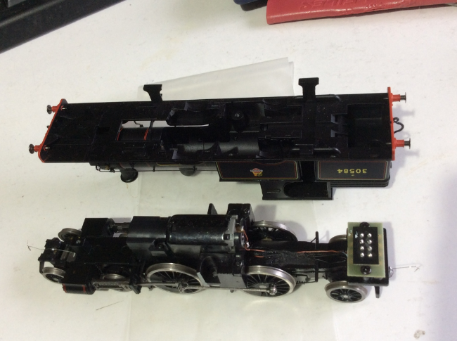
I used the Alan Gibson LNER K3 conversion wheelset for the replacement drivers (AG code: 4800/23). Be careful ordering the rear radial wheels; the size varies between locos (30583 has smaller wheels matching the bogie). To remove the tight-fitting body from the chassis, 2 screws need to be extracted from under the tanks plus one from the chimney (but I understand that this does not apply to all models; I did not re-use this chimney screw as from previous experience it could lead to body distortion). Care needs to be taken not to overtighten the 2 screws under the tanks or you can distort the cab. Against all expectation, I found no digging was needed for clearances. This loco is really well engineered and balanced by Hornby. It is tempting to try and add a lot more weight, but it really does not need it and you might upset the overall weight distribution. I added a chunk of lead between the firebox sides under the keeper plate as this is central and should not upset the loco balance. I also added a brass bush to weigh down the rear axle of the bogie as it tended to rise. Unlike others, I do not seem to have a problem with gradient changes or undulating track (of which I have plenty!) but if you do, the perceived wisdom is to reduce the thickness of the bogie washer or even remove it. I kept the bogie pick-ups and toyed with the idea of adding pick-ups to the trailing radial axle. My recommendation is do not bother with the complication! The most awkward part of the conversion was fitting AJ couplings; these ended up being secured to the NEM pockets with handrail knobs.
I am not a DCC fan. Space for a DCC coder is provided in the bunker but the fit is very tight; ask others which chip to use. The coal and tank filler are easily levered out to reveal a proper floor for the coal. I guess this could be removed to make more space for a chip. Hopefully technology improvements will allow me to fit small (stay-alive) supercaps in the bunker some time in the future.
In terms of negotiating awful sharp radius trackwork and steady slow running, the Hornby Adams Radial out-performs my heavy brass split-axle Adams 02; most upsetting!
Attachments:
-
July 25, 2025 at 12:36 pm #252086John CutlerParticipant
Hornby Adams Radial Conversion Notes 2
Tip. If you convert a loco to EM and know you have to do another of the same class, then make copious notes. I now wish I had written up a Manual Sheet for my first conversion of the Hornby Adams Radial. A couple of years later and I had forgotten all the pitfalls! The penalty is I scrapped one set of driving wheels and wasted a lot of time on my second conversion.
The front drivers need 8mm crankpins. Alan Gibson no longer sell a long crankpin so buy them on eBay (M1 bolts: cheap!). The rear drivers are OK with standard AG 6mm crankpins.
The front screw of the keeper plate retains the bogie. The rear end of the keeper plate holds the radial axle. You may need to pull these out after taking off the keeper plate; the chassis is then easier to handle. The valve motion just clips in the top of the chassis and can be lifted out. The cylinders are retained with a tacky black glue by Hornby and should pull forwards and off easily. Try to keep and re-use that glue to hold them when replacing; Black Tack should do a similar job. Detach the motor and its worm.
The first job with Alan Gibson wheels is to cut the axles to the correct length; AG no longer do this. The wheel depth is 2.3mm net of boss and a 16.5mm Back-to-Back gives an axle length of 21.1mm (I use 21.3mm because I use a 16.6-16.7mm Back-to-Back). I used a mini-drill with a cutting disc (wear eye protection!) to grind from the side of the disc (not as a slitting cutter; yes, I know it is bad engineering) and cheap diamond-coated mini-files for this (filing alone takes for ever!). Chamfer the ends of the axles slightly to help prevent them digging into the plastic wheels.
I decided to restrict the lateral movement of the front driving wheels so as to ease any pressure on the gear. I duly carefully measured up the clearance from the side of the chassis casting and fitted spacing washers. Big Mistake! After assembling everything, I discovered the keeper plate refused to fit. So I pulled the wheels off the axle and rectified. But as is usually the case for me with AG wheels, refitting resulted in unacceptable wobble so they were scrapped.
The front drivers do not need spacing washers at all. The tight splasher clearances mean the axle can hardly move laterally anyway. This lack of clearance means the gear needs to be positioned on the axle somewhat precisely. Do not twist the gear on or off the axle; push it (otherwise the roughened axle acts as a file). Roughen up the area of the gear location on the axle with a coarse file by rolling it up and down a couple of times on a cutting mat. I recommend placing the axle and bearings in the chassis and marking the possible position of the gear with a marker pen. Then carefully keep the filing within those limits, especially on the shorter side with the thinner bearing; you do not want any roughened steel axle running in the brass bearing. Take your time, position the gear with the axle (and bearings) in the chassis and measure the projections of the axle each side of the chassis to ensure they are equal. Try to ensure the gear sits on the centre of its mating gear and has roughly equal possible movement either side. Adjust the gear as necessary before adding any adhesive to the gear (if the centre of the axle is roughened up sufficiently with a file, glue may not be needed).
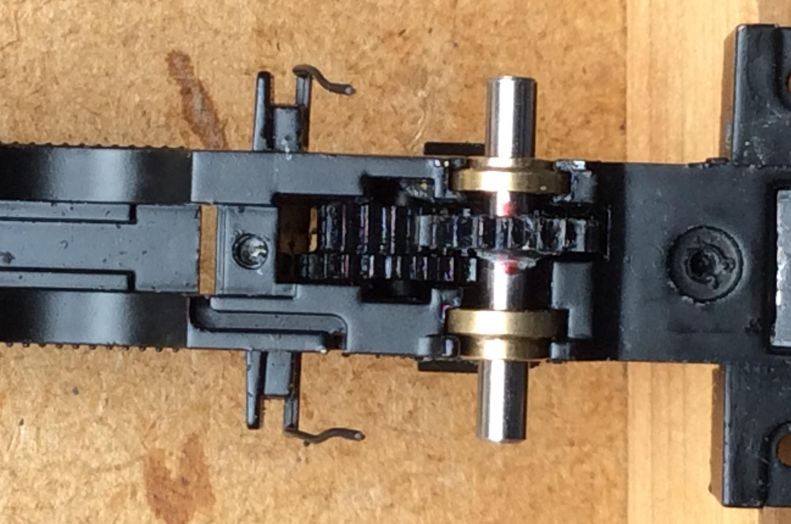
The axle centred about the chassis with the gear wheel centred on its mate. The red markers define the limits for roughening the axle with a file. Note the thinner bearing on the offset gear side. The photo shows up some gunge on the gear which has subsequently been cleaned off.
I decided to play safe and put a 1mm spacing washer on each side of the front driving axle anyway; it adds a bit of weight too. I also put 1mm thick washers on the rear drivers just to stop the axle waggling about too much but I am not convinced they are really needed either.
When assembling the front axle, be aware that the Hornby bearings differ in width on each side (this does not apply to the rear drivers). The 8mm long crankpin means that I could not use the GW wheel-press to quarter the front drivers. I quartered them by eye using Sellotape then closed the wheels up to the Back-to-Back gauge using a small vice; see separate post on Quartering. Do not fit the balance weights before quartering.
Ensure the balance weights are of thin material and do not protrude beyond the tyres. If they do, they will foul the splashers; clearances are minimal.
For the front driver crankpins, I cut lengths of 2mm o/d 1mm i/d brass tube to 3 mm long to act as bushes; +/-0.1mm is probably OK. The Hornby coupling rods are 1.3mm thick. 0.2mm needs to be filed off the back of these at both ends (you need the clearance at the rear wheels too). The con rods should be 1.3mm thick; I had to file down the back of one to reduce it to that. I put a Romford crankpin washer 0.3mm thick over the crankpin (you could use a 12BA washer but it is thicker), followed by the tube. The coupling rod is then placed over the tube, followed by an M2 washer (0.4mm thick) and the con rod. This lot was then secured with a 12BA washer with an M1 nut (not 14BA; why do people persist in using the incorrect thread?). This fits nicely on the 5mm protruding crankpin with a minimal but comfortable running clearance for the rods. You could gain 0.2mm by using a Gibson nut but nowadays I use a standard M1 nut if I can; less hassle, less likely to drop off and easier to find and refit when it does. The only issue is that they do not always darken with Gun Blue. I have no clearance problem with this arrangement. Subsequently I found the M2 washer too obtrusive (4.7mm dia) so discarded it. I suspect that is not good engineering but my first Adams Radial conversion works fine without an intermediate washer.

Wheels in place and crankpins loaded with rods and secured. The photo reveals the Hornby bearing on the right is narrower than that on the left. Here the wheels are equidistant from the chassis. In any other position they are likely to foul the splashers and/or the gear will rub against either side of its travel. Line the gear and axle-ends up before adding and quartering the wheels. M2 washer was omitted after this photo was taken, as it is too big viewed side-on.
The rear driver crankpins protrude about 3.1mm. I used a short AG crankpin bush and cut a 1.4mm long brass bush out of 2mm o/d 1.5mm i/d tube to fit over that. With the thinned coupling rod in place, this is secured with a 0.3mm thick Romford crankpin washer and a 1.2 mm thick M1 nut. This gives about 0.3mm running clearance for the rods. This could be reduced by shortening the tube by 0.1mm so there is some leeway when cutting the tube. An alternative would be to solder an AG coupling rod insert bush into the rod instead of the tube, which is difficult to cut to such a short length. I find it trickier to solder these inserts into the rods so tend to avoid them if I can (but they are useful for other purposes!).
Apply a drop of lubricant to the Hornby bearings and to the crankpin bushes.
At this stage I recommend checking the quartering by adding the drivers to the chassis and adding the coupling rods. Neither add the con rods (preferably take the valve assembly off the chassis if not already done) nor the keeper plate. The bearings are a tight fit in the chassis so the wheels should stay in place. Just gently propel the chassis to and fro by hand. Do not assume any lumpiness is just a quartering issue; check the rods are straight, have smooth vertical edges in contact with the wheels/washers at the crankpins and are not fouling anything like balance weights or axle ends.
Now I know I was lucky with my first conversion. The splasher insides of the front drivers of this loco needed lengthening. It is obvious that the Hornby assembler had difficulty matching chassis to body. There is evidence of grinding down the cast boiler and splasher to clear the wheels for OO, let alone for EM. Fortunately, I only needed to carefully file down plastic not metal.
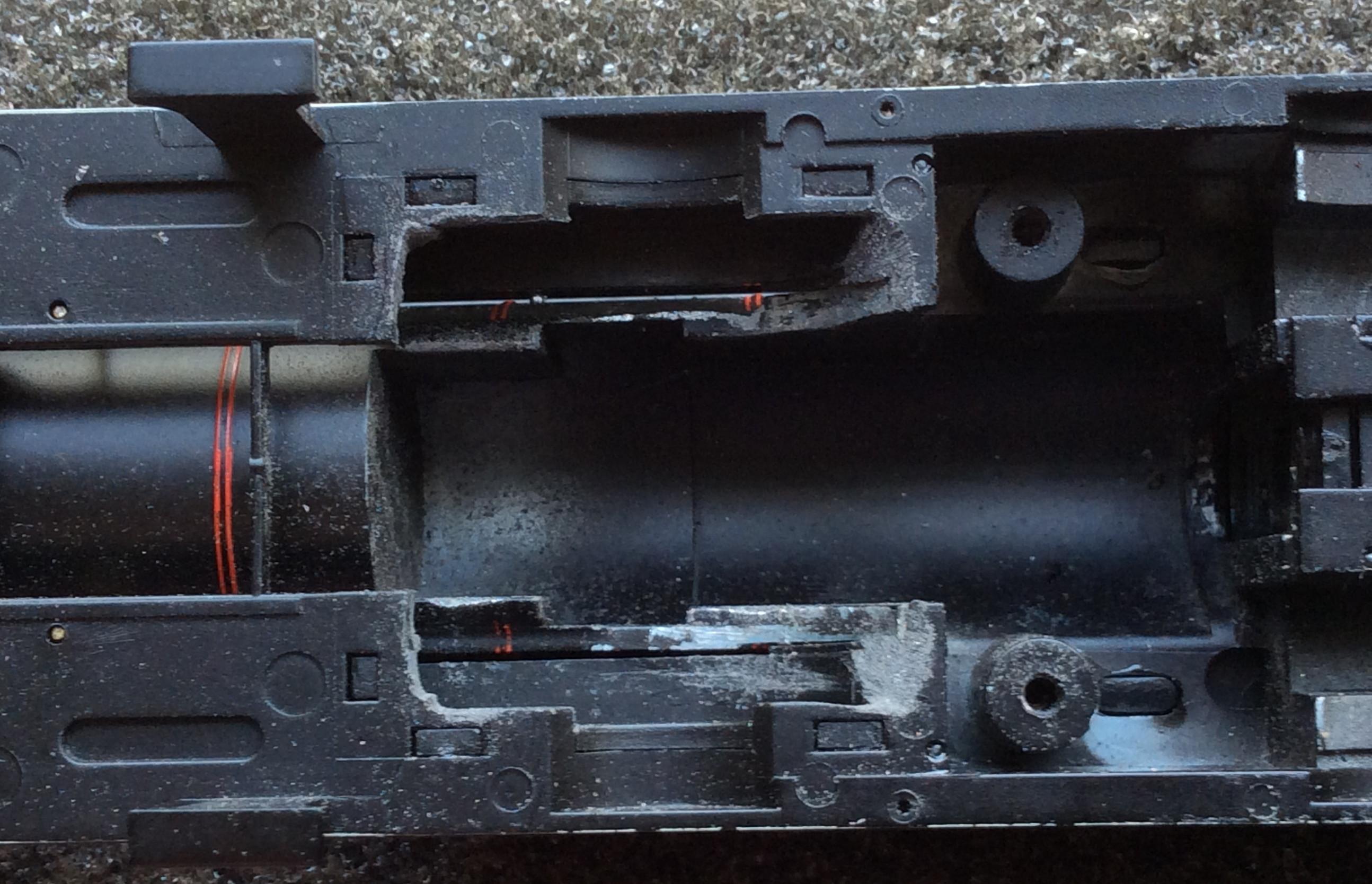
Carving out of the inside ends of the splashers to clear EM wheels. Note the bare metal where the Hornby assembler has ground it out to fit OO wheels.
I reckon a conversion to P4 will require the splashers to be widened as well as be potentially lengthened. P4ers gain up to 1mm extra clearance by using a narrower wheel than EM which perhaps compensates for the 1mm+ greater Back-to-Back. A small deficiency will result in the wheels clouting the splasher sides. Additionally, AG wheels are sometimes wider than the 2mm P4 standard. If the P4 wheelset ends up being wider than the EM one, not only will the splashers have to be widened, but the components on the front driver crankpin may have to be thinned and the pin shortened.
Offering up the keeper plate to the chassis, it will soon be apparent that the brake shoes foul the wheel flanges. There are 3 ways to tackle this:
1. Cut off the brake shoes and replace with etched versions from Wizard (MT182 SR Loco brake shoes). The shoe supports must not be removed as the new shoes need to be pinned and glued on to them. Pin, do not just rely on glue; the shoes have to support the brake actuation gear. I suspect this method will be required for P4.
2. Carve the shoes to shape with a knife. I have read of people doing this, but it must be difficult with such plastic. I would be frightened of the knife slipping.
3. File the shoes to shape. An (expensive) riffler file is useful. Ordinary flat files are liable to damage the brake supports but can be used; I used them as well as the riffler. Use a file with a single cutting edge if you can, as that reduces the risk of collateral damage. The filing is awkward. You need care and patience!
Test each wheelset separately in the chassis with the keeper plate attached; omit the pickups. Avoid trapping the Hornby sandpipes between the wheel and the brake shoes as you do so. Test by rotating the wheelset in both directions; it is surprising how often a blockage is found to be one-way! A trick to finding that once per rotation obstruction is to watch the bottom hangers of the brake shoes as the wheel turns. If one twitches slightly, it tells you that brake shoe is responsible. Ensure the wheels turn freely before proceeding further.
There should be a little lateral movement of the wheels possible after this. If you file/carve the brake shoes back, this will be minimal but with etched shoes more clearance is possible.
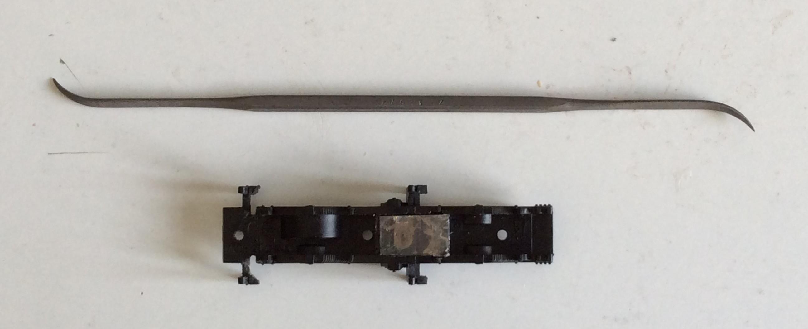
The front brake shoes have been carved to 45 ̊ at the back to clear the wheel flanges. The rear brakes show the original square profile. The tool used is a riffler file; this one has no cutting teeth at the sides and rear so there is less chance of inadvertently cutting through the brake supports. I ended up filing away a lot more of the front brake shoes than shown here to ensure the drivers turned freely. Note the lump of lead inserted between the ashpan sides.
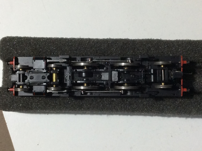
It is worth testing the free-running of the chassis again. Leave off the con rods, the cylinders and the pick-ups.; this narrows down any problems. If there is an obstruction, it is often possible to sense where it is if the chassis is slowly and gently propelled by hand. Ensure the coupling rods are straight and have not been bent by handling. Add the pick-ups and repeat the test.
Spacing washers were added to the bogie front axle and to the radial truck to minimise any lateral movement and help guide the following wheels. I allowed more movement on the rear bogie axle and again added a large bush to weigh it down. This time I also added a thin bush to the front axle. Note the aim is to add weight to the bogie itself in order to improve its road-holding. I do not recommend changing the light springing of the bogie; that might upset the good balance of the loco.
Reassemble the motor and its retainers. Test run the complete chassis before fixing to the body.
Reassembly is a straightforward reversal of dismantling. Despite adding a little Black Tack to the Hornby black glue, one of the cylinders kept dislocating. I applied a tiny amount of superglue to the cylinder’s topmost surface join with the chassis to try and stop this. I do not recommend applying superglue instead of the tacky glue underneath as you will most likely foul up the bogie attachment and spring. As well as permitting dismantling, the Hornby tacky glue is a clever way of allowing the bogie some lateral movement but acts as a damper.
If you choose to use the chimney screw to secure the body, I recommend not to screw it in tight. Allow the body to flex a little.
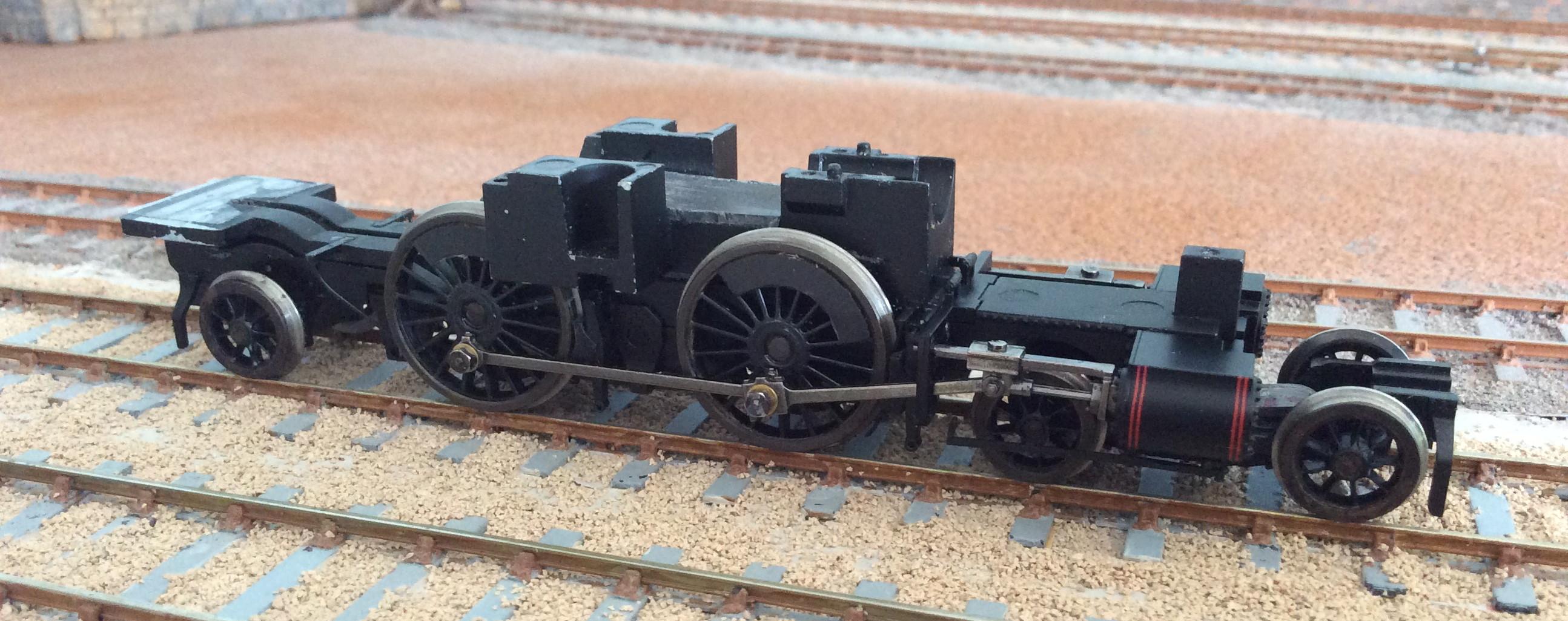
Note the pickups and wiring have been stripped out and the motor is awaiting fitting. This chassis is destined for radio control -hopefully a separate article will shortly appear in the Radio Control forum. Brake rodding is still to be fitted. Oddly two of the M1 crankpin nuts took Gun Blue but not t’others despite being from the same batch. They were darkened with black marker pen.
-
August 24, 2025 at 7:51 am #252297
Geoff Stenner
ParticipantCan I just comment on the wheel choice? I have converted an Oxford Rail Adams, and used the Gibson 18 spoke 5’6″ wheel because:
A It will look the part because over the flange it will be closer to the 5’7″ of the original than a 5’8″ wheel.
B. I think there is a minute reduction only in crankpin throw which eases any problem of rods bashing the underside of the footplate without visual loss or loss of crosshead movement.
Just an idea.
-
August 24, 2025 at 9:53 am #252298John CutlerParticipant
No-one produces the correct driving wheel in EM for the Adams Radial Tank: 5’7” diameter, 18 spokes, crank In-Line with spokes, and, I think, a 14” crankthrow.
I followed Pete Hill’s recommendation to use the K3wheel; 5’8” dia, 18 spokes, Pin Between spokes and 13” crankthrow. The smaller crankthrow compensates for the larger diameter wheel’s effect on the piston travel. The larger diameter wheel potentially gives problems with splasher clearance. Strangely I had no problem with that on my first conversion but suffered with my second! The slightly reduced crankthrow gives less chance of the crankpin fouling the footplate and I had no problems with that.
In service, these tanks would often run with worn-down wheels to a 1” smaller diameter. If a 5’6” dia wheel is used, it seems to me that visual compromises are required. The obvious alternative is the M7 wheel which has the crank In-Line but suffers from a much-reduced 9” crankthrow. This would look odd in motion, not just at the crank but at the lack of piston travel. The S15/H16 wheel has bevel rather than plain spokes. The Met E wheel should look OK with a crankthrow of 11.5”. But is it available with 3mm axles to suit the Hornby chassis (note the Oxford Radial chassis can use 1/8” axles)? There is no AG conversion set listed for it.
I wish someone would produce splined EM axles to suit Hornby’s wheels!
-
-
AuthorPosts
- Only logged in EMGS members can reply to this topic