› Members Forum › Layout Wiring and Control › Radio Control › Scalefour Society R/C kit harness
- This topic has 6 replies, 1 voice, and was last updated 9 months, 1 week ago by
John Cutler.
-
AuthorPosts
-
-
October 30, 2023 at 8:37 am #247017
John Cutler
ParticipantI have successfully fitted the S4 Society R/C kit to a Gibson Adams 02 and am in the process of fitting 2 more to a Connoisseur G6 and a Bachmann N. For tank locos I am finding the harness is horribly long and voluminous. One result is that if the 02 body is separated from the chassis, on re-assembly it takes 15-20 minutes to carefully stuff the harness back into the limited space available so it does not protrude, foul anything or be in danger of coiling back to do so. The G6 was originally built conventionally and is stuffed full of lead, some of which is now being extracted. I want to keep wiring out of the chassis as far as possible, as the previous pick-up wires succeeded in fouling the csbs and I ended up with a loco looking like it was poised for take-off! The harness, as well as the receiver, is going to have to be installed in the G6’s cab so I want to minimise the volume and coiling.
Has anyone adapted the harness or made their own? I may have a go at making my own but am worried about soldering tiny 1.27 pitch connectors and insulating them. I guess that means crimping the connectors and heat-shrinking the covers on them. Does anyone have recommendations for the tools and material required?
Also has anyone substituted the harness crossover connector (with a PCB?)?
If this is tortuous or expensive, I may ask Micron if they can oblige. I reckon I will ultimately need a dozen or so smaller harnesses.
Thanks in advance for any advice or useful URL links.
-
November 30, 2023 at 7:39 am #247391Participant
I guess not many are into radio control yet, so there is not much experience evident in the use of the ScaleFour Society R/C kits. My issue is that the kit consumes far too much volume to be useful for a tank loco conversion. My first conversion of a Gibson 02 drives me spare whenever I have to reassemble the chassis to the body as I spend a good 15 minutes carefully prodding the harness back into place ensuring it does not foul anything. I bit the experimental bullet and bought some sockets from Micron and played around with the idea of replicating the S4 Soc harness with a shorter version. It quickly became apparent that this requires some nifty soldering so I investigated the possibility of using a pcb or similar which probably requires the same but with more potential for saving space.
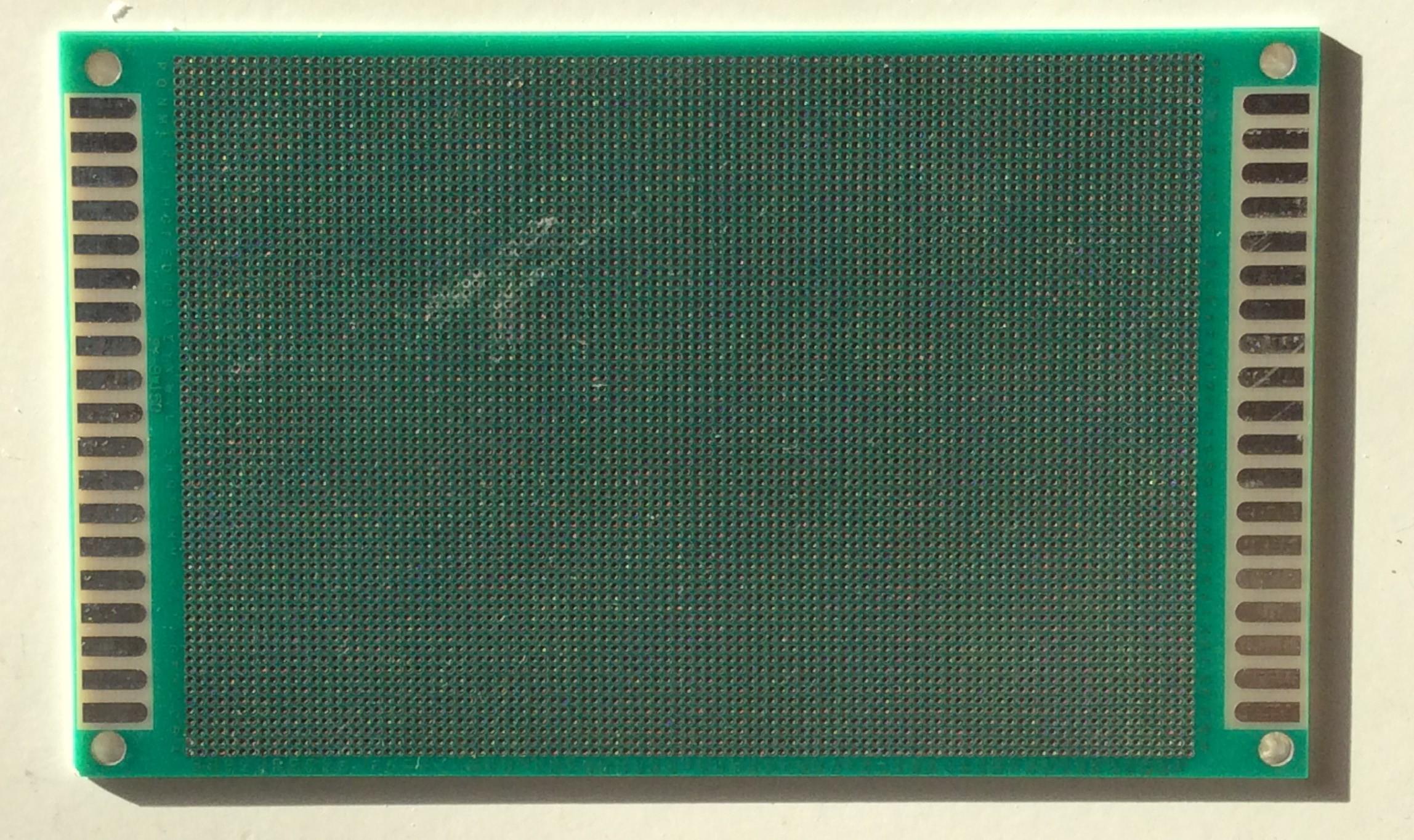
I bought a 1.27mm pitch perforated board which replicates the pitch of the kit’s Micron plugs. My original intention was to make up a board that the Micron connectors could plug directly into. This involved soldering three 0.45mm nickel silver pins onto the board. Then connecting these and the holes needed for sockets on the reverse of the board so as to replicate wiring. The YouTube guides on electronics soldering suggest that you do not need wires for this; it is possible (easy, even!) to trail the solder from one perforated socket to the next. As a convicted bodger, I found this to be impossible. Maybe this is because I used a lead-based electrical solder? I resorted to using 0.45mm wire to connect the sockets which resulted in a ham-fisted mess. Despite this horror I managed to produce a miniature working circuit free of shorts. The process of joining the perforated sockets filled them with solder. Drilling them out, to allow access for the Micron connector pins, duly cut the wire connections! Moreover the 3 pins soldered to the board were considerably adrift from the desirable 90̊ so plug connection was going to be difficult. A different approach was needed.
Requirements for the Mark 2 job:
1. 1.27mm pitch double-sided perforated board, £8.15 from Amazon including VAT and postage from China (so delivery is 10-14 days).
-
November 30, 2023 at 7:42 am #247392Participant
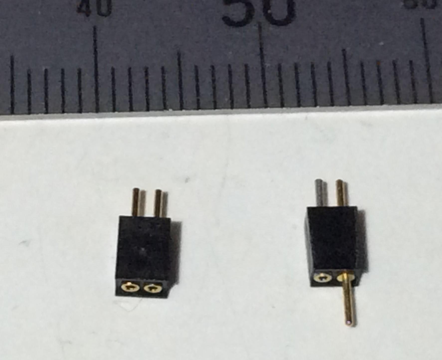
2. Micron 2-pin 1.27mm pitch polarised connectors. These have 2 pins at one end and a pin and a socket at t’other; the 2-pin end is glued to the perfboard. They come in packs of 5; you need 3.
-
November 30, 2023 at 7:45 am #247393Participant
3. Micron 2-pin 1.27mm pitch socket connectors SKU 53184. These have 2 pins at one end and 2 sockets at t’other. They come in packs of 5; you only need 1, for the switch connector.
4. A pinpoint soldering iron for electronics work. I recommend an iron with a flexible silicone cable for this tiny application. I bought a new bit for my Antex 25W iron.
5. c0.5mm solder wire for electronics soldering. I may have made a mistake in buying cheap lead-based solder for this job; I suggest investing in top quality electronics solder.
6. Araldite epoxy or other slow-setting glue.
7. 0.45mm and/or 30 AWG wires, unless you can trail the solder between the perfboard sockets.
8. Some paper and/or Blu-tak and maybe tape to use as soldering blocks.
9. A junior hacksaw to cut the perfboard to size.
10. A magnifying glass on a stand.
11. A circuit tester.
12. Three pairs of hands.
13. A swear box.
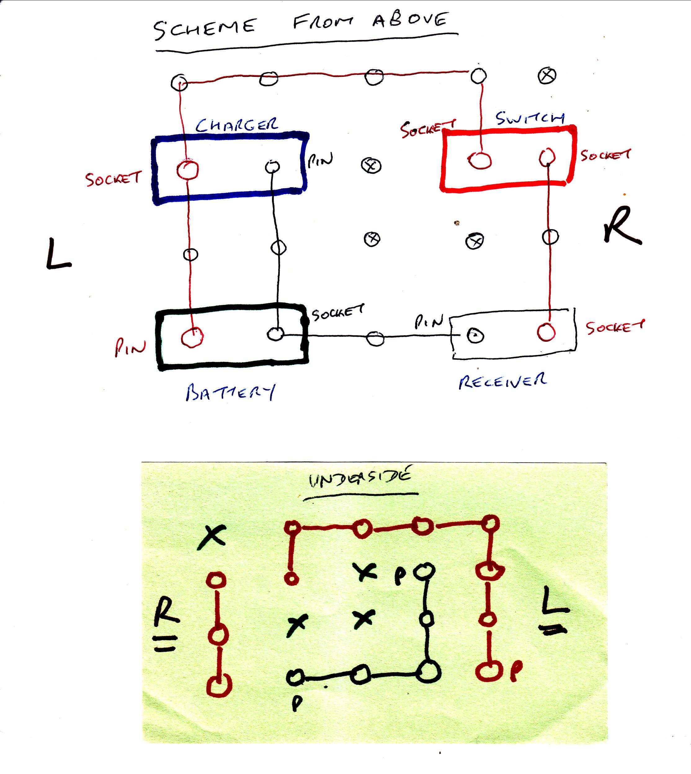
The Mark 2 version employs Micron connectors glued to the perforated board (refer to the wiring diagram below). Do not use a quick-setting glue like cyanoacrylate as there is a danger of misconnecting the tiny pins at the first attempt (how do I know?!). I used Araldite. I recommend placing small pieces of card (cereal packet) between the Micron connectors to act as spacers otherwise they will tend to end up, like mine, being too close together. Note the S4 Soc connectors are thicker than the Micron ones due to the use of a heat-shrink wrap; I ended up removing some of that otherwise the pin connections were too awkward. If you can afford the extra space (another 1.27mm on the board width), leave 2 perfboard sockets unused between the plugs rather than the one I left unused (shown on the wiring diagram below). Make sure the pins protrude on the reverse of the perfboard; they do not poke out much. After the glue has cured, soldered connections can be made at the back of the board; between the protruding Micron pins. I used 0.45mm and 30AWG wires. Refer to the diagram below. A combination of Blu-tak and bits of taped paper were used to block possible solder misconnections; you need an exceptionally steady hand for the iron not to drift or wobble a tiny bit. Test at every connection. Then test again for possible short circuits.
-
November 30, 2023 at 7:47 am #247394Participant
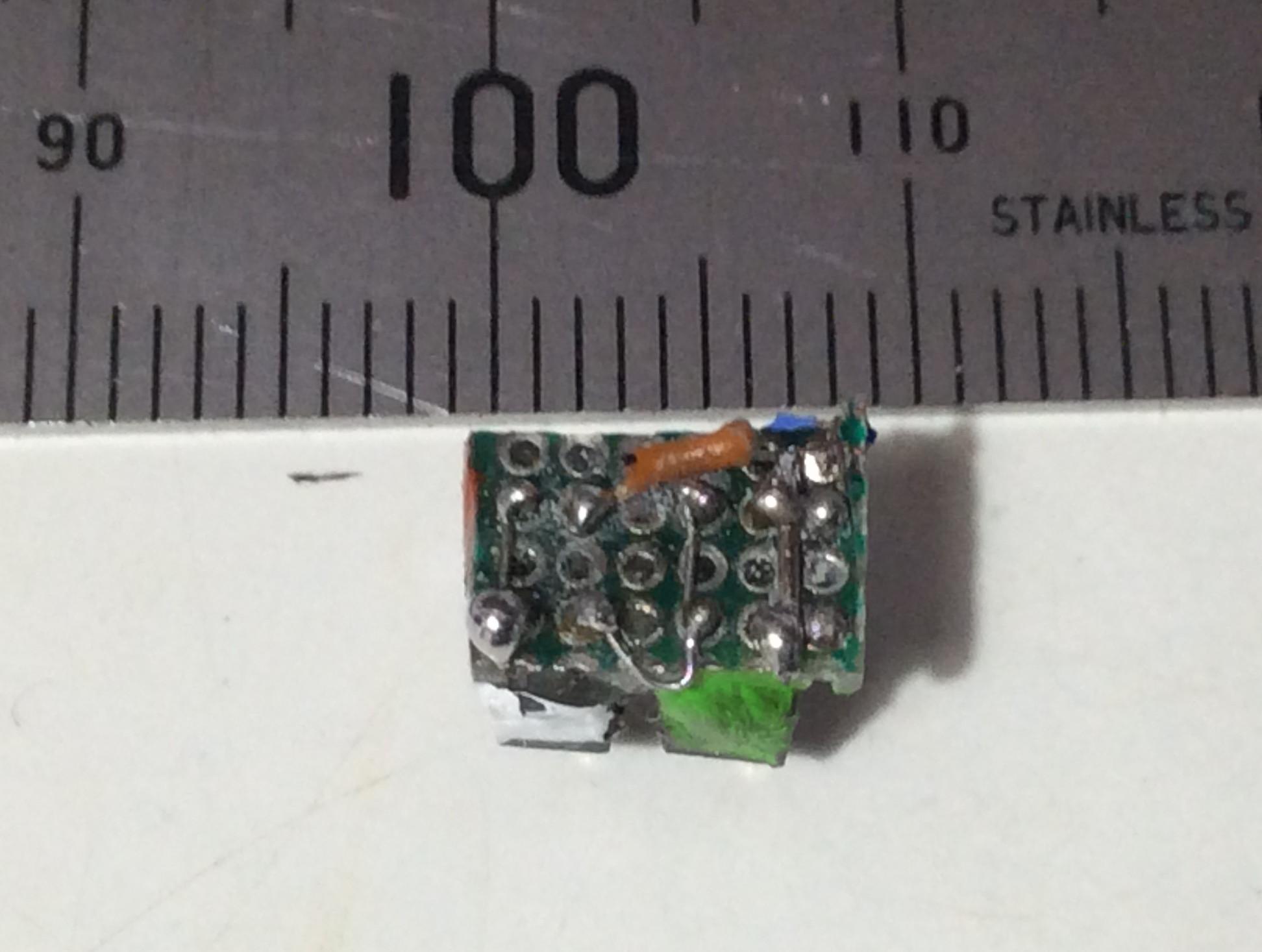
Having completed the wiring, carefully saw out the perfboard; it is easiest to mark out and follow the line of the next unused sockets. Check the circuitry again; I inevitably managed to saw through one protruding wire! I recommend colour-coding the Micron plugs on the finished assembly; I used acrylic paints. Whilst you have the paints out, I suggest colour-coding the matching plugs on the wires to the battery, receiver etc.
Here is my awful handiwork (I beg tiny mitigation, miLords):
-
November 30, 2023 at 7:49 am #247395Participant
The wiring needs to be protected with tape. I find most insulating tape useless for this sort of job so used Tamiya masking tape for the rear with an overall secondary seal of 3M Magic Tape which allows the colour coding to be seen.
Here is the difference in volume betwixt the S4 Soc harness and the perfboard alternative:
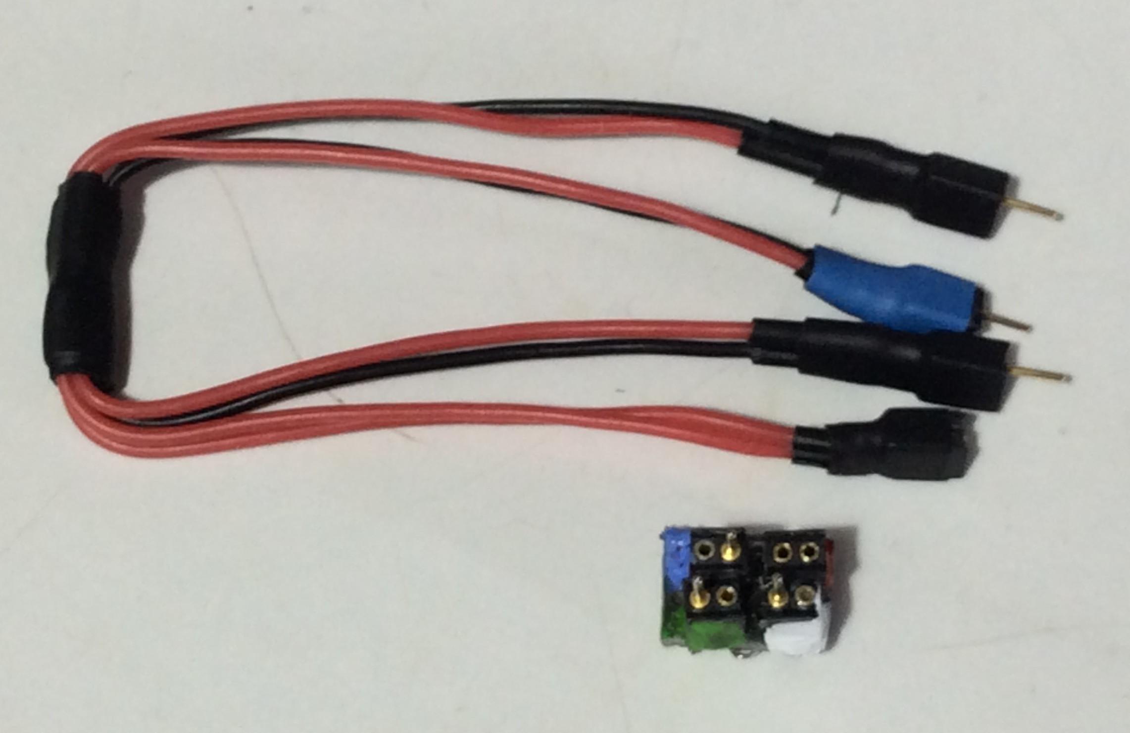
-
November 30, 2023 at 7:50 am #247396Participant
Be careful handling the receiver. The aerials dropped off both of the two receivers I have fitted so far and I had to try to solder them back on with only a 50% success rate. More tiny soldering! Ugh! Removing the clear hard plastic covering to get at the tiny aerial connection pad is also a pain; take care not to cut into the pcb. Surely the aerial arrangement could be a bit more robust or serviceable? Luckily I had a spare receiver awaiting loco conversion No.3. After binding this to the transmitter, I promptly pushed some Araldite onto the aerial anchor point to try and secure it (the end of any warranty).
Would I do this again? Probably not (at least for some considerable time). The truth is that this drove me nuts; soldering is fraught for me at the best of times. But for a tank engine, especially a retrofit like the G6 where I had to dig out lead to make space, I had no choice unless I hard-wire all the R/C components. Now I have 2 tank locomotives with radio control, I will convert some bigger locos with lots of space in tenders for the harness etc. I await a more tank-loco-friendly R/C kit.
Hopefully this article may give others some ideas.
-
-
AuthorPosts
- Only logged in EMGS members can reply to this topic