› Members Forum › RTR Conversions › Locos › Notes on converting the Bachmann N mogul to EM
- This topic has 3 replies, 2 voices, and was last updated 6 months, 4 weeks ago by
John Cutler.
-
AuthorPosts
-
-
February 13, 2024 at 8:43 pm #247988
John Cutler
ParticipantPART ONE: PRE-AMBLE
These notes are supplemental to the EMGS Manual 3.2.6.(3).
I successfully converted one of these 23 years ago following Tim Shackleton’s article in MRJ112 and the EMGS Manual. I always felt that this guidance left a lot to be desired, especially for a relative novice like me at the time. I am now converting another, and hope these notes help anyone who wants a useful Southern mixed traffic loco in EM. The end result is worthwhile: a powerful workhorse just like the prototype. Up against the buffers my first N once propelled the flexitrack rails underneath across the room! Frightening. The secrets of its traction success are the weight, springing of the centre drivers, the powerful Buhler motor sitting upright in the firebox and 60:1 gears. Its down sides are that it does not like dips or peaks in the trackwork (like my lousy PW workmanship) or A5 turnouts and under (probably due to not allowing enough side-play on the middle drivers).
Before you start:
1. In my view this is not a simple conversion, contrary to the impressions given by Tim Shackleton and the brevity of the EMGS Manual Sheet. If this is your proposed first conversion to EM, I recommend instead you try converting a simple inside-cylinder model first; the Bachmann LMS Jinty or 57/87XX GW panniers are ideal.
2. This conversion may not be for you if you want a perfect representation of an N. Most of the Bachmann model’s shortcomings; oversized lamp irons, lack of separate handrails on the front of the tenders etc, are easily overcome or are forgiven by the average modeller. However the fake firebox sides are part of the Mazak body and, without an engineer’s workshop, are nigh on impossible to remove easily and successfully (the bracket is actually on the prototype but Bachmann support it with unprototypical widened firebox-side extensions to hide the fat but powerful motor). Secondly you must compromise on driving wheel authenticity unless you make your own -see below.
3. Make sure your N is not suffering from Mazak rot. This is a known problem afflicting the footplate or chassis block. Spare chassis blocks can be bought direct online from Bachmann at £10. If the footplate needs replacement, a whole body spare costs £53 so it will probably be worthwhile considering buying a complete second-hand N instead.
4. Check your N runs smoothly in OO. If the N does not run well for any reason, dismantle the loco, clean everything and take out the motor. If you slowly push the chassis along by hand, any unwanted contacts, displaced or bent rods etc should become apparent. Listen for knocks or scrapes. The quartering should be OK unless someone has previously dismantled the wheels. If there is still a problem, check that the axle-ways in the chassis are parallel and at 90 ̊ to the frames. If you cannot or do not know how to do this, buying a new chassis block might be a worthwhile precaution. However, unlike some other old Bachmann models, the N is not known for this problem so buying a new block may be unnecessary; you have to take a risk either way.
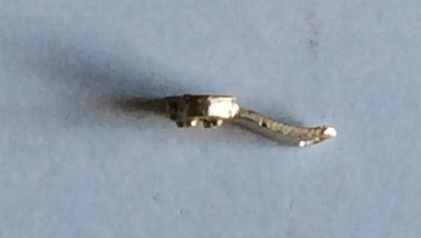
5. If bits of your N are dodgy or missing, Bachmann hold a surprisingly good stock of spares for this loco (perhaps because it has been in production for so long). I was concerned about the state of the valve gear/cylinder assembly on mine so purchased a spare for £20 (it was needed!).
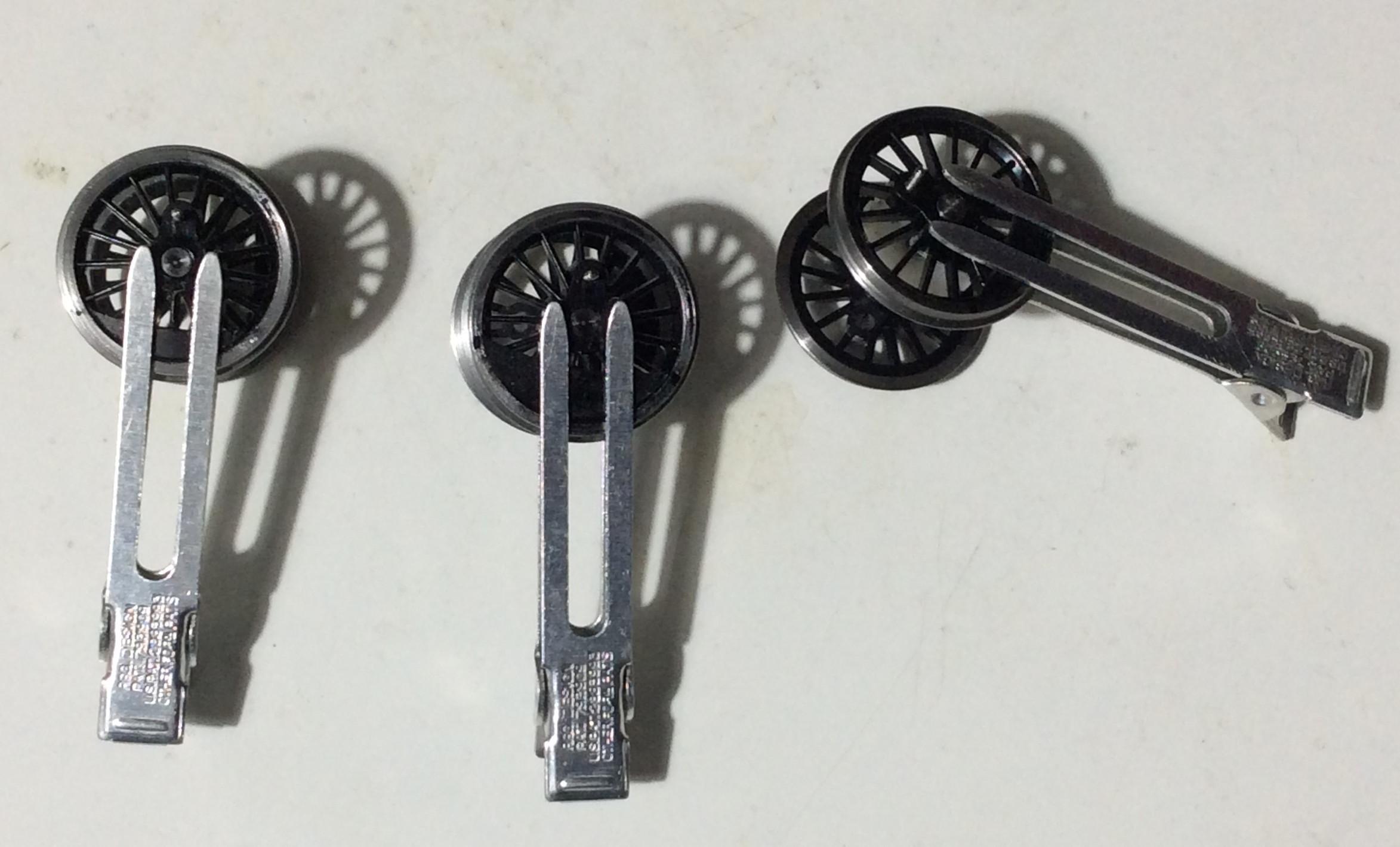
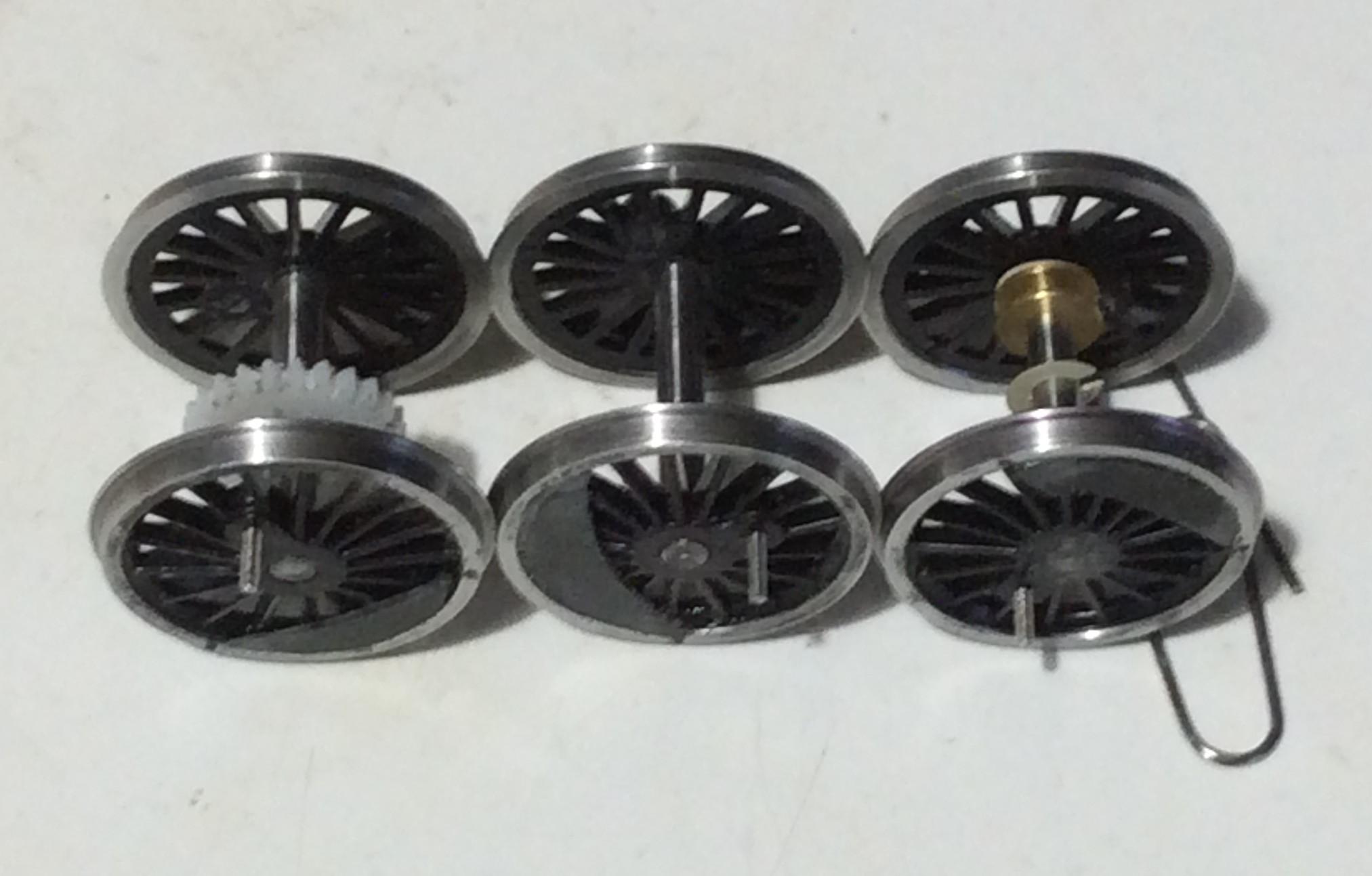
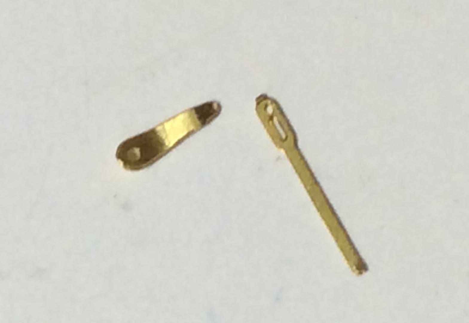
There are no true-to-scale replacement wheels available for the N. The Bachmann drivers have 17 very fine spokes and are true to the real thing with a 13” crank-throw. The tyre is around 0.7mm thicker than a finescale wheel. More importantly the effective flange width is around 0.8mm compared to the EMGS standard 0.55mm for an AG wheel so crossing flangeways narrower than the EMGS standard of 1mm are not a good idea perhaps. The EMGS Stores advertise a conversion shouldered axle of 2mm to 3mm diameter (code 5905) which means it is possible to re-use the Bachmann wheels. The Bachmann axle-ends are splined. You could try abrading the new axles but I strongly suspect wheel slip will be a major issue. I recommend also applying Loctite 603 to the axle but after (tricky) quartering. This is not for me. Using ordinary 3mm axles is not possible because the Bachmann drivers are all-metal with an insulating plastic axle insert. The Alan Gibson conversion set wheels (MR Flatiron recommended by the EMGS and as used by Tim Shackleton) are for a short crank-throw of 11”. Visually I prefer the motion to be correct; I think it is noticeable. I opted for the LMS Stanier Mogul conversion wheelset 4800/64. This has the correct throw of 13” and Pin Between but at the visual cost of bevels. The Crab wheel also has a 13” crank-throw but at the penalty of the crankpin on a spoke (IL) rather than between spokes (PB) and a pronounced boss; too much for me and likely to give trouble with clearances. You could try the LNER K3 wheels which have a 13” throw and Pin Between but have 18 spokes rather than 17; the wheels are 5’8” rather than 5’6” so the loco ride height will be higher by 0.33mm; these wheels look a lot bigger to me. The boss is less pronounced than the Crab wheel but more so than the Stanier wheel. Its visual plus is the spokes are much finer and are comparable to the Bachmann wheel. You must choose the visual compromise that suits you. Note that Rumney Models recommend the S15 wheel which has a 14” crank-throw (which might give problems with the cylinders), PB and 18 spokes and bevels; it is only available with 1/8” axles not 3mm. It is surprising no-one, not even Mike Sharman, has produced a proper finescale replacement wheel for the N or a replacement splined EM axle so the Bachmann ones can be re-used.
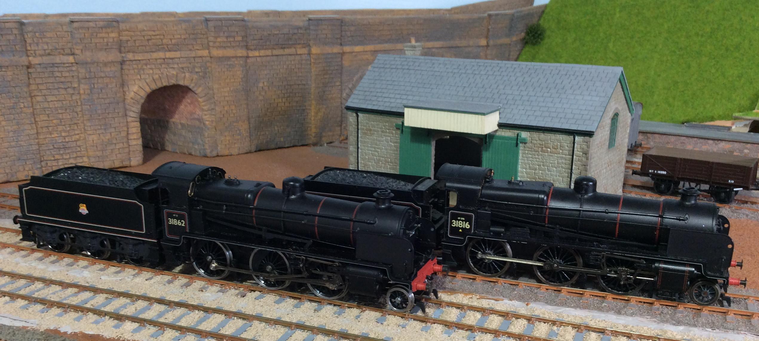
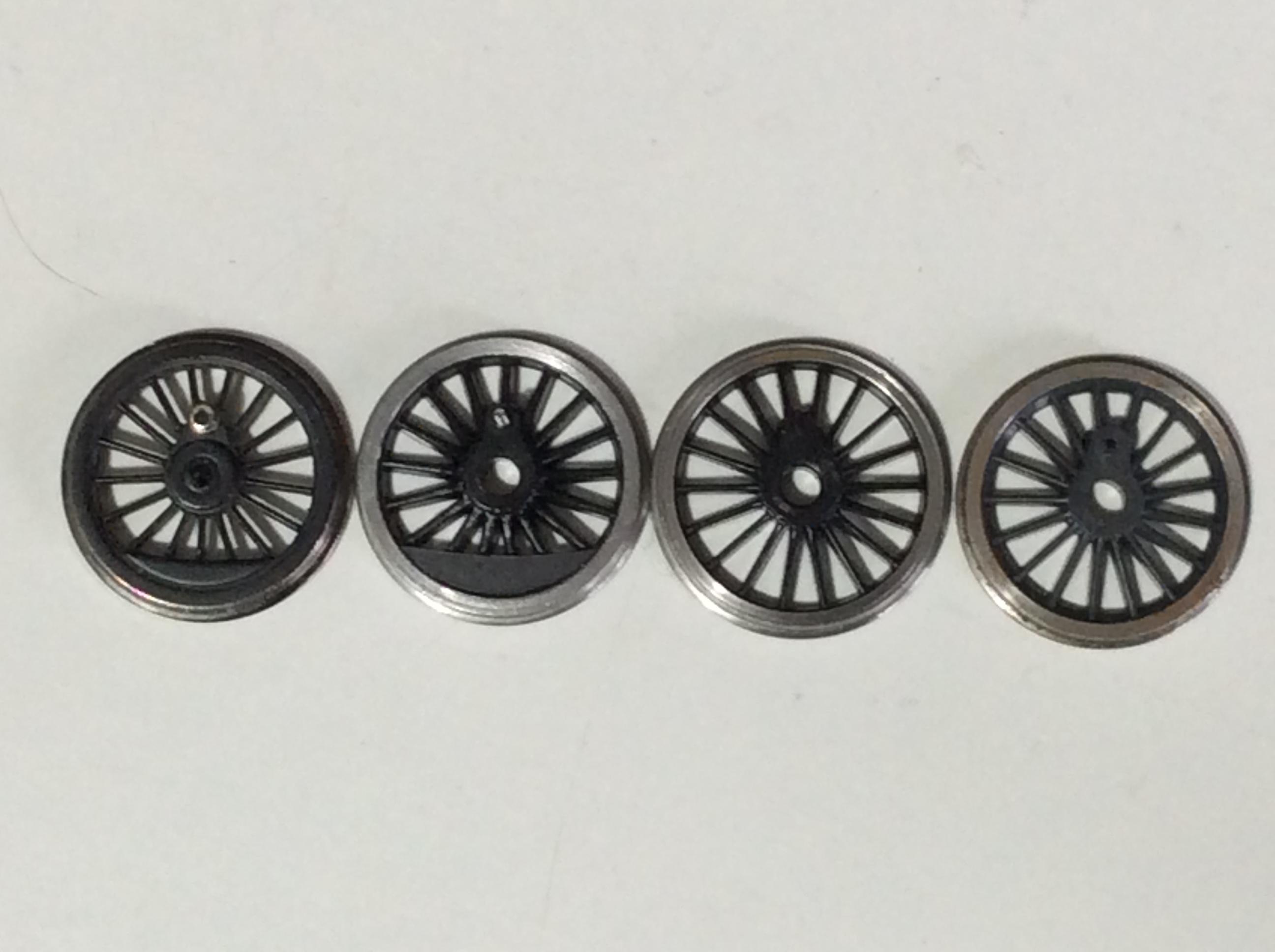 From left to right: Bachmann; Crab, K3, Stanier. Note this Bachmann balance weight is symmetric about the crankpin, unlike their centre driver (see photo below).
7. Check if you need 12-spoke tender wheels rather than 10-spoke. If you change the tender type, double-check against a prototype photo (if you are bothered)!
8. I also ordered the Gibson return crank for the N (4M822). The reviews of this I have seen have been unfavourable. I think the perceived problem mainly arises because people try to use a 14BA tap on the crank to fit it to an M1 Gibson crankpin. I used an M1 tap and had no problems. An M1 taper tap used to be very expensive but I see a titanium coated one on eBay for £5.63, less than a third of the price I paid over 2 decades ago! I am aware of comments that re-using the Bachmann crankpin and crank is fraught. Experimentally I tried extracting the Bachmann pin with the wheels held firmly in a vice and the darned pin disintegrated. Otherwise you need to make a crank from nickel silver and either solder it to the crankpin or tap it M1! OK, without an M1 tap you could drill a 0.85mm hole (maybe 0.9mm+ is needed but try 0.85mm first) and gently try to wind the crank squarely onto the crankpin.
9. You will need (expensive) Loctite 603 to secure this crank in position. 601 is OK but is not oil-resistant. Superglue might be OK but I would not risk it. Note 603 has other uses like helping secure the driving wheels in position.
10. A set of small drill bits that include 0.85mm diameter for drilling crankpin holes in AG wheels, pre-drilling the new eccentric rod crank for tapping and for the rivet hole.
11. Valve gear rivets are needed for fixing the replacement return crank to the eccentric rod. Short ones from Alan Gibson are OK.(code 4M50).
12. The standard AG crankpins are supposedly 6.5mm long but are more often 6mm. You need two at least 7.5mm long for the centre driver. You can buy countersunk M1 stainless steel screws 8mm long very cheaply on eBay. For comparison, the Bachmann crankpin is 7.9mm long plus the length of the crank retaining screw.
13. You need some brass or bronze or nickel-silver tube with inside diameter of 1mm and an outside diameter of 2mm to form bush bearings for the centre driver crankpins.
14. You also need AG coupling rod inserts (4800) for the Bachmann rods; these act as bearings. If you decide to replace the Bachmann coupling rods, be aware that scale ones will be thicker and you will have fun with clearances (as I did with my first conversion!).
15. If you decide on replacing the Bachmann rods, note the LNWR alternative suggested by the EMGS Manual is, as they state, incorrect; you need to fabricate new rods e.g. from AG’s universal rods. Wizard’s 7’3”x7’3 coupling rods (MT001B @£2.40) help make this easier for the jointed short 7’3” section of the rods. I replaced the Bachmann rods on my earlier conversion with finer scale ones. The Bachmann cranked coupling rod is eliminated and this means the conn rod does not need to be cranked (refer to the diagram a long way below) so the big end can be thinned down (as per the EMGS Manual). The AG crank at the end does not have to be double-cranked. Congestion there is reduced so it looks better and there is less likelihood of rods clashing. The downside is that because the coupling rods are thicker, clearances on the front crankpins are horribly tighter. I managed to get this to work (after days of cussing!) but the result is that the whole motion is tight even if smooth; it needs the powerful motor to budge it!
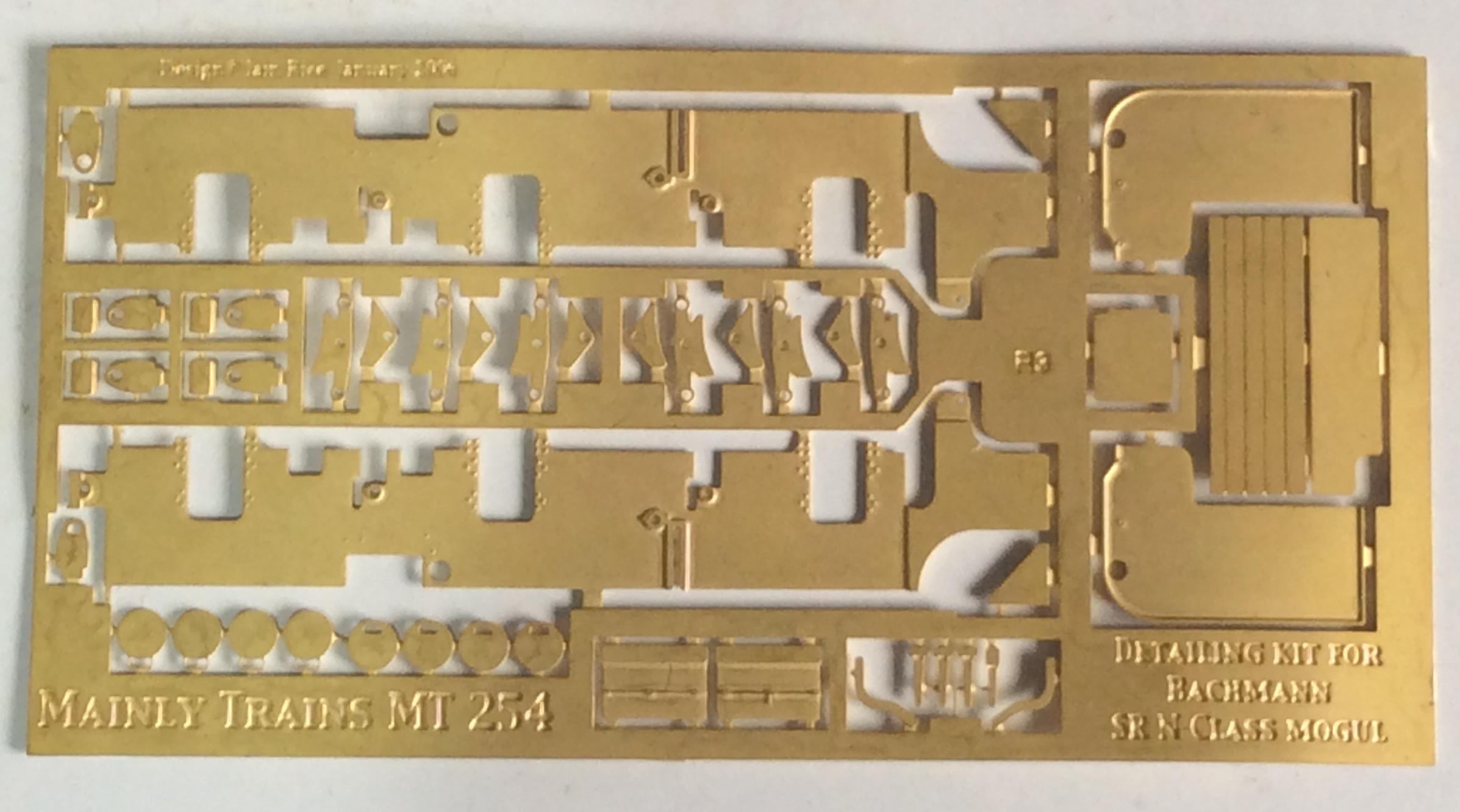
16. I bought the Mainly Trains detailing kit from Wizard for the N (MT254) thinking this might help for my second conversion. In retrospect I do not think this is worthwhile. The cosmetic frames do not align with the correct Bachmann wheelbase so are useless. The total wheelbase is out by 2mm (a surprising design error by Iain Rice). I will not use the etched brake gear as the Bachmann brakes are fine by me (I might use the brake brackets as tank lifting lugs on my tank engines). The AWS shield will not be fitted as it interferes with any auto-coupler. The only parts I will definitely use are the lamp irons and maybe the fall-plate. Looking though many photos of Ns, I usually cannot see the cab doors so I may not fit them. Likewise I am not sure I can be bothered to replace the smoke deflectors, although the etch does look marginally better.
17. You need to plan how to convert the tender (this is where it gets complicated). You cannot use the existing chassis without widening it. The width between the Bachmann frames is only 21.5mm. At least 0.4mm needs to be filed off each side around the wheel apertures to fit EM wheels. The centre axle needs a lot more for side-play or it will derail on curves.
The options:
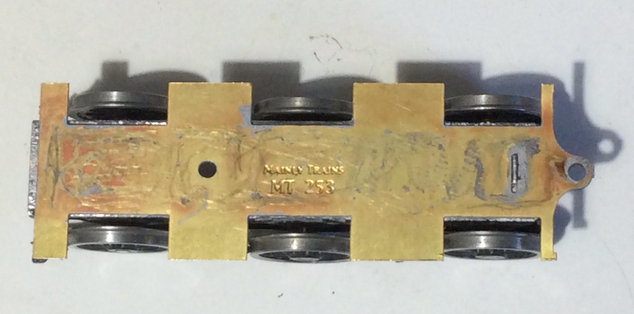
a} If you have the ordinary 3,500 gallon tender, you could buy the Mainly Trains tender chassis kit for the N: MT253 (from Wizard). This replaces the cosmetic outer frames and provides an internal frame but no axle-box/spring castings (unless you can get hold of an old kit). The nearest similar are probably white-metal castings for the N1/U/Schools now re-released (on sale at the Portsmouth show in November 2023) by the new owners of ABS, Modelstock; these need a small amount scraped off the bottom to be correct for an N, methinks.
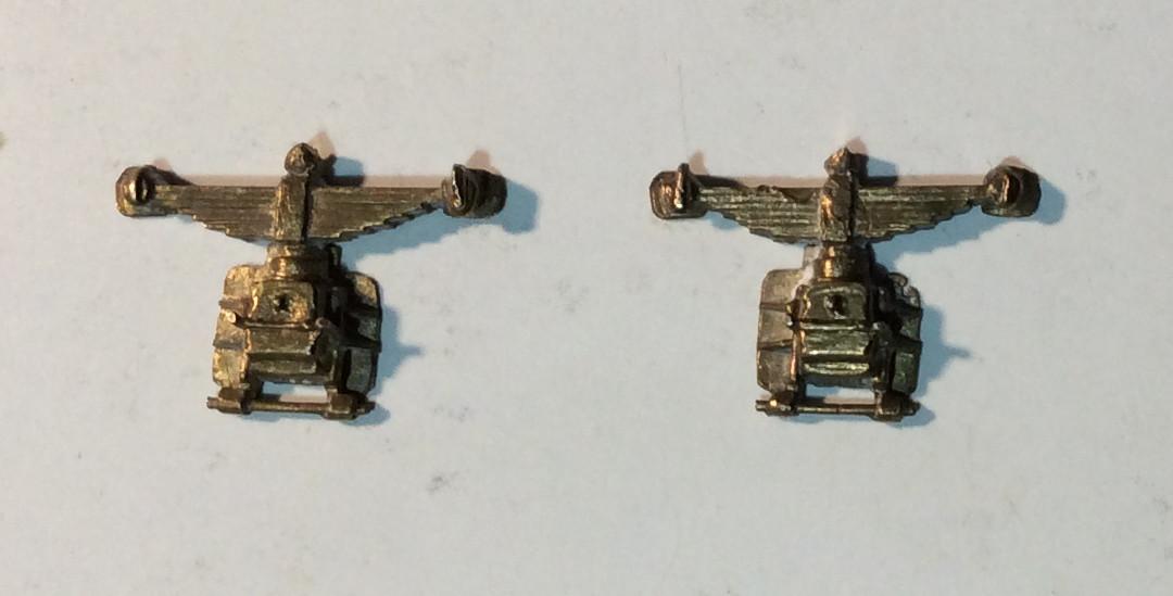
These are the old brass Mainly Train axlebox castings no longer available; the Modelstock white metal castings are similar.
Note the Mainly Trains chassis is not compensated. The unmodified MT chassis allows for some vertical movement of the centre axle. The Mainly Trains chassis fits neatly inside the 3,500 gallon tender body (but not the 4,000 gallon one); no modifications to the body are needed. This is the simplest conversion solution, and the one followed in these notes. However, I suggest you read the description and conclusion below before you commit.
(b) The EMGS Manual suggests widening the tender frames and then making up a functional internal frame to carry the wheels. No guidance is given on making that internal frame. Widening the existing frames is not straightforward as there are strengthening brackets across the chassis. These are best reinforced across the cut chassis and the new central widening strip. The simplest way to do this is to make a secondary thick plasticard floor above and across the joints. Then eliminate much of any obstructive brackets so a level floor is created which a Comet 6’6”x6’6” chassis kit TC1 can support. If you are going to all this trouble, you may as well consider making this into a split-frame chassis so you can dispense with pick-ups on the tender.
(c) On my first N conversion, I combined a sprung Perseverance chassis (you can use the Comet TC1 chassis from Wizard instead) with the existing outside frames. The frames were sliced along the inside and the centre chassis discarded. About 1mm was cut off the remaining narrow floor attached to each side so that the frames were more widely set. These were then glued to the tender body. A separate floor was then made from PCB and scored twice longitudinally to create a split frame. Another piece of PCB scored identically was used as the frame spacer for the Perseverance chassis. The Gibson tender wheels were fitted with EMGS etched shorting wires (Stores code 4910) and split axles. A split-frame chassis guarantees frictionless electrical contact with the rails. I can recommend this approach but it is hardly a simple conversion; I made lots of mistakes!
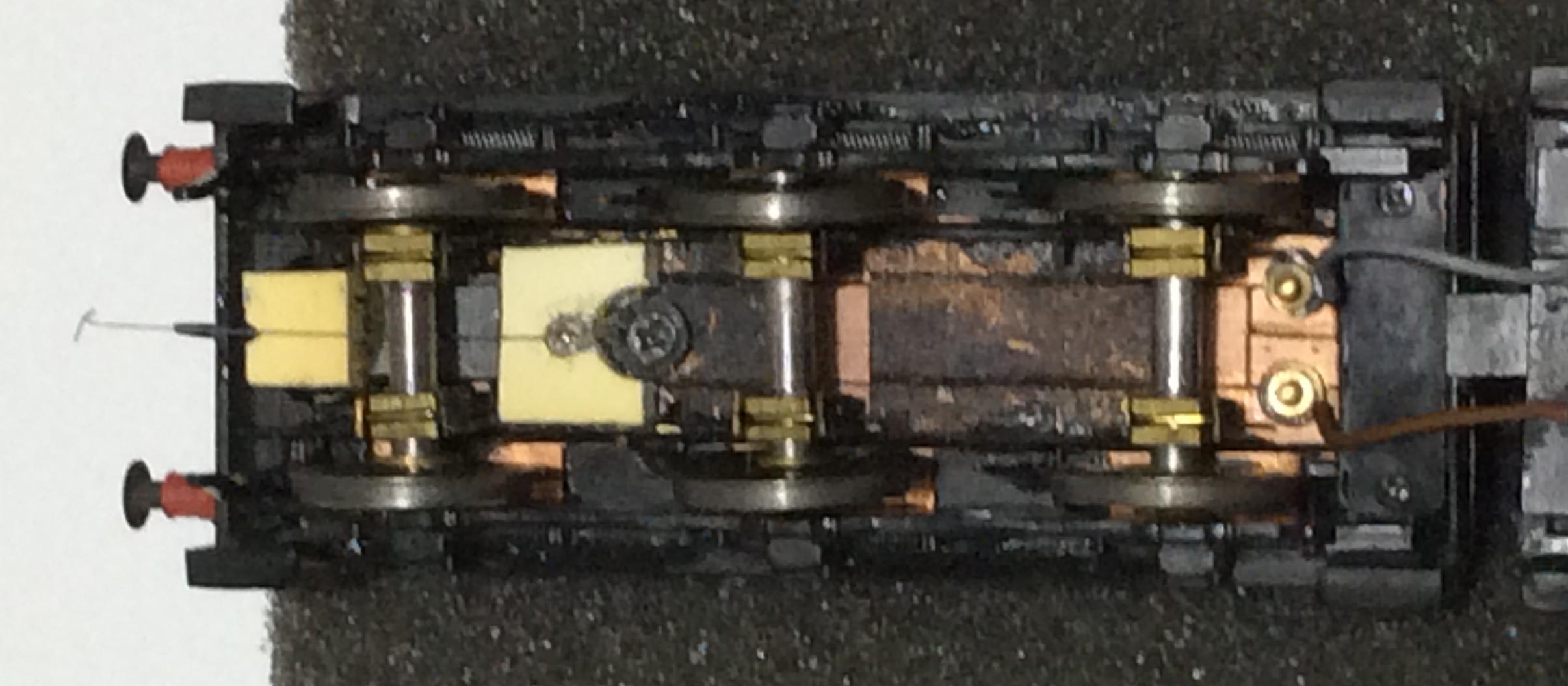
This is the underside of my old 3,500 gallon tender with original plastic frames widened and a split subframe using a Perseverance chassis. Sprung too; I do not remember how I did that (25+ years ago!) but the axles are 1/8”and wheels with those are no longer available. No brake rods; I wonder if they are in a drawer somewhere waiting to be fitted! Note I reused the Bachmann drawbar.
(d) The new kid on the block is the Rumney Models tender chassis kit for the N (£14). This has Continuous Spring Beams (csbs) and fits internally between the frames. So you still have to cut out and widen the Bachmann frames for re-use but you do not have to worry about strengthening these as the Rumney chassis provides cross supports. This kit is a lot more sophisticated than the Mainly Trains chassis so will require more work but is probably a good simple introduction to csbs. The tender should run smoothly. The designer (as seems usual for kits) makes no provision for pick-ups despite being more elaborate. The brake gear is correct for the 4000 gallon tender but not for the 3500 one in original condition; the GA drawing in MRJ112 and the PMA one in RailDigest5 both show horizontal uncranked brake rodding. No doubt some Ns acquired the later cranked variety, with rods at differing angles, on overhaul of their 3500 tenders. You need Miniblox hornblocks from High Level for this chassis.
(e) If you have the Bachmann 4,000 gallon tender and wish to convert it, then I am afraid this requires more work. You need to widen the frames as above. The brakes are moulded onto the frames so they too obviously do not align with the wheels. This is one of Bachmann’s poorer designs. Cutting these off the thick frames needs a lot of care not to damage the spring supports and the guard irons. Two brake actuators are provided but one should be removed; only one can line up with the brake standard on the tender floor. I would be inclined to remove both as after the frames are widened the brake actuator’s misalignment with the footplate brake standard will become obvious.
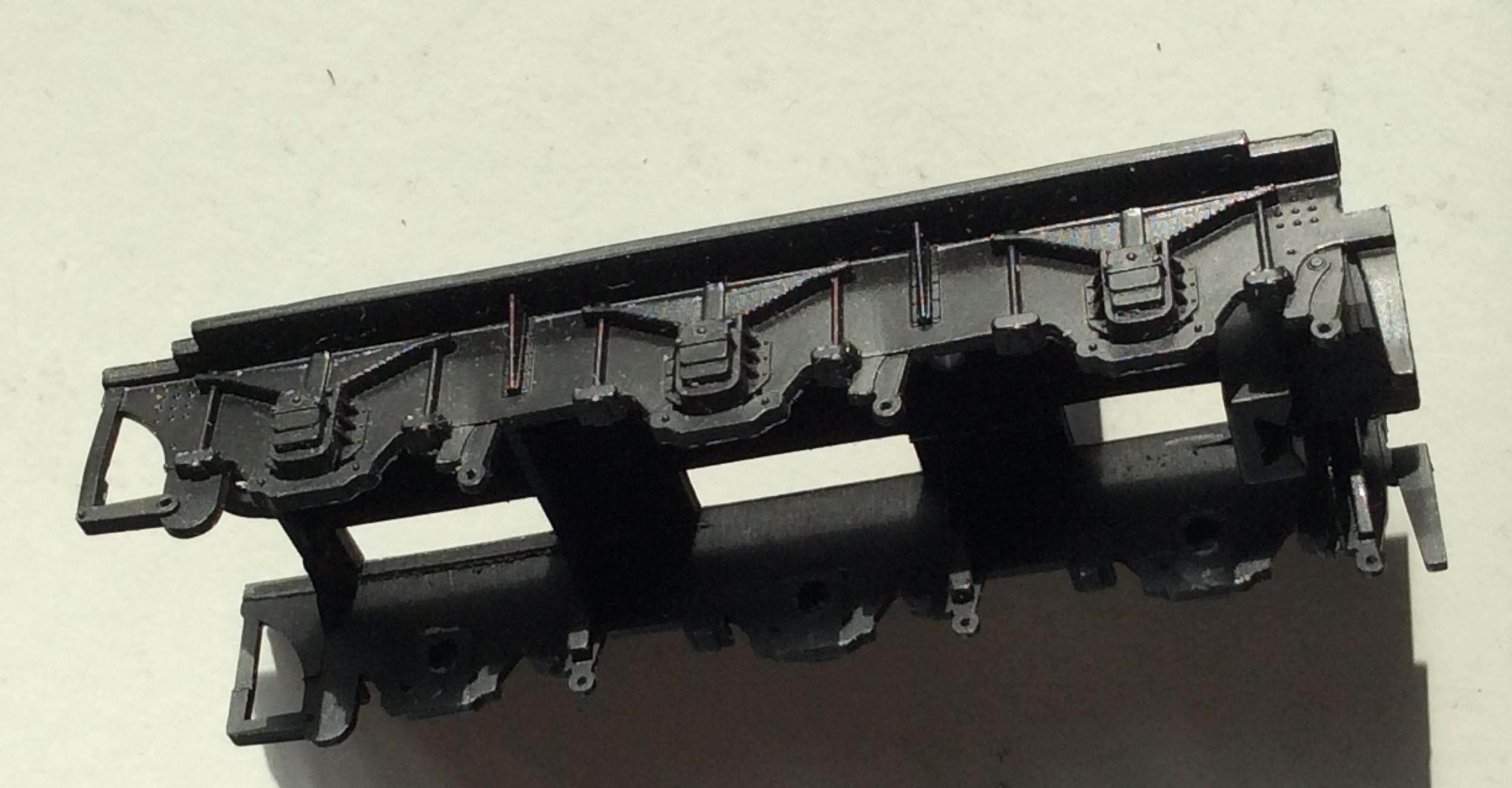
Bachmann 4000 gallon tender chassis needing careful carving
I suggest that a Comet or Rumney sub-chassis be used with this.
{f} Tim Shackleton converted a Hornby Schools tender to the N 4,000 gallon one. If you follow that route, be aware it requires a fair amount of bodywork carving and reconstruction. The fall-plates of the N and Schools do not align. There is a step in the side of the Bachmann 4,000 gallon tender body so it matches the loco. The Schools tender needs to be modified to replicate that and to align the footplates. Not only does this mean carving and a repaint but also some tricky lining, especially if you desire Southern Railway livery. The Bachmann drawbar arrangement must be replaced.
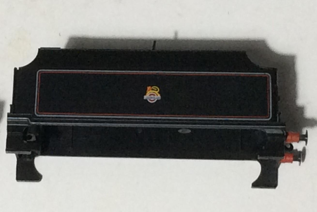
Bachmann N 4,000 gallon tender body showing step up in bodywork and lining.
18. Tools you will need:
1. A soldering iron. You need this to fit the AG bearings to the coupling rods and for electrical connections at the very least.
2. An EM Back-To-Back gauge.
3. A caliper gauge.
4. Taper cutting broaches.
5. Pin vices to hold small drill bits and the M1 tap.
6. A small hand drill for drill bits 0.5mm to 2mm.
7. Needle files.
8. A large coarse file for abrading the centre driver axle for the gear wheel.
9. A cutting mat.
10. Small precision screwdrivers.
11. A piercing saw and spare blades (they break easily!).
12. An M1 taper tap for the replacement AG cast crank.
13. A Stanley knife or craft-knife or similar for cutting plasticard.
14. Cutters (e.g. Xuron) for removing the valve gear rivets and shortening steel crankpins and other screws/bolts: I use old ones for this; new ones will be ruined cutting hard steel.
15. Tweezers and pliers.
16. Paintbrushes.
17. A razor saw for widening the loco keeper plate and the tender frame.
18. A solid metal flat surface that can be safely bashed; it does not have to be big; for fitting rivets to the new crank.
19. A small mirror e.g. ladies compact.
Desirable tools:
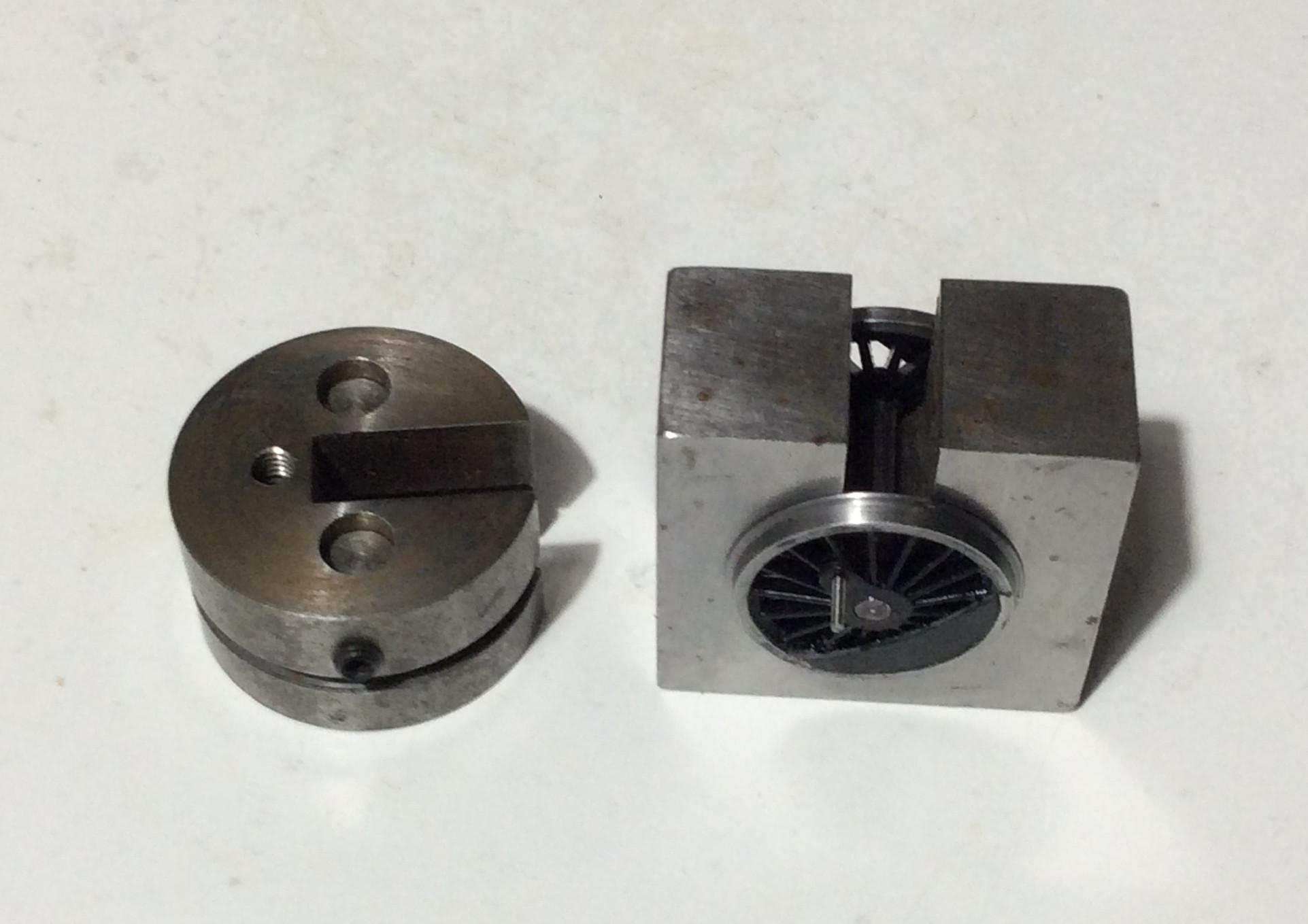
1. GW quartering jig.
2. Olfa compass cutter.
3. A 2mm reamer.
4. A small vice.
5. A GW adjustable BTB gauge (read below) additional to the fixed one (above).
6. A permanent black marker pen e.g. Sharpie, for blackening (wheels etc).
7. A centre punch (for rivets).
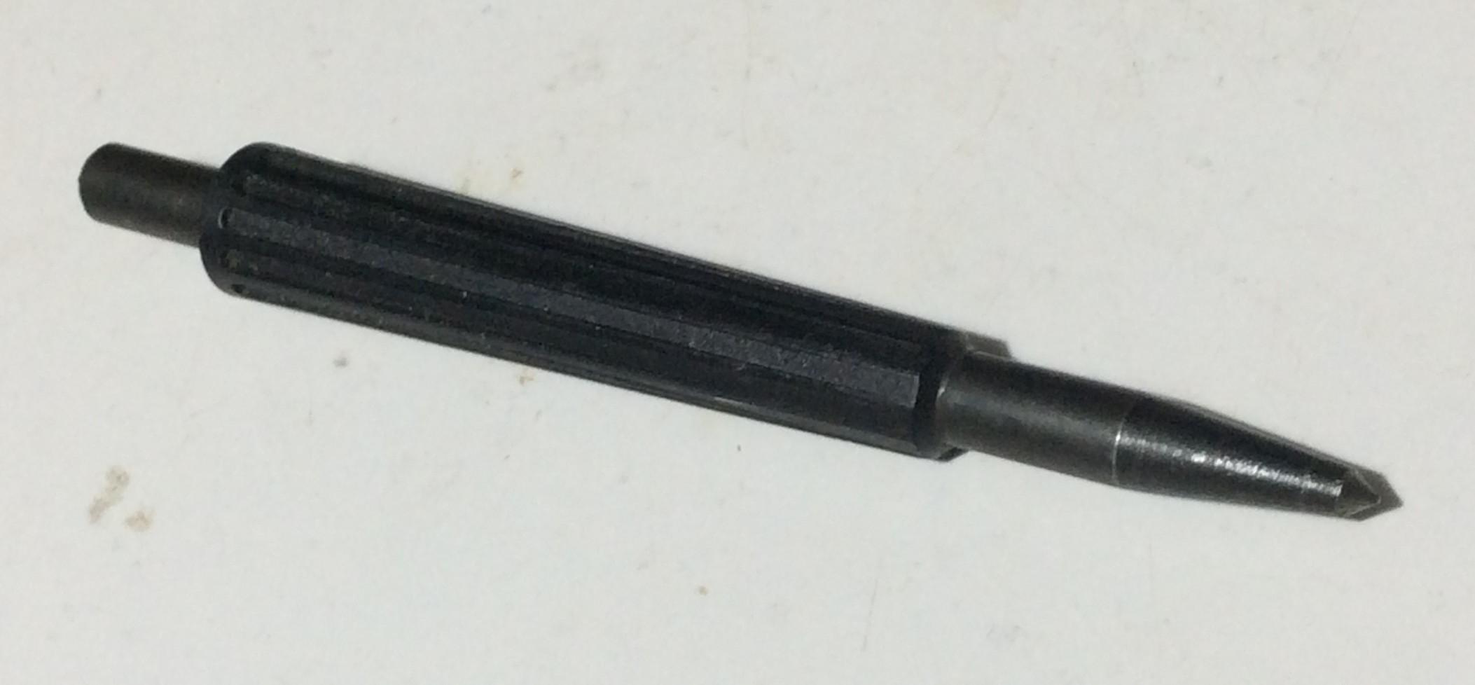
Note the wide angle of the point of this centre punch which helps splay the rivet.
A BUDGET £
Chris Kedgeley (RIP) would not approve if I do not give an idea of costs!
These are at December 2023 prices:
£
Alan Gibson: Loco conversion (wheel) set (your choice) † 32.50
G4836 3’ dia 10-spoke bogie wheels (for pony truck) 3.70
3’11” tender wheel 10- or 12-spoke x3 11.10
4M42B crankpin set for 6 wheels * 6.70
4M822 cranks for centre drivers 5.20
4M50 short valve gear rivets 4.70
4800 coupling rod inserts (bearings) 3.00
Subtotal 66.90
† Note the EMGS conversion sets are cheaper but availability is limited.
3,500 gallon tender Mainly Trains option:
Wizard MT253 N tender chassis 13.50
Modelstock Maunsell U/Schools tender axleboxes & springs 5.00? Subtotal 18.50
Either tender internal frames options:
Wizard Comet TC1 6’6”x6’6” wheelbase chassis kit 6.00
Rumney X.16A N tender chassis subframe 14.00
High Level 3 pairs 2mm MiniBlox for Rumney chassis @£3 9.00
*Also available from the EMGS Stores.
So minimum total of £73 plus extra for damages/shortages and consumables. Not a cheap conversion!
PART TWO: THE LOCOMOTIVE
If you have not already done so, check the chassis runs freely in OO. If there is an issue, dismantle the body and motor and try running the chassis manually. If it seizes or jerks once per revolution then check for obstructions to the coupling rods or valve gear. Try disconnecting the centre driver cranks and connecting rods (better still, remove the valve gear subassembly and cylinders altogether) and see if that resolves the issue; buy a new assembly from Bachmann?
If the OO chassis still misbehaves, then the problem lies either with the coupling rods or the axle centres in the chassis block. It is extremely unlikely to be the quartering (unless someone has previously dismantled the wheels) as this is set precisely in the factory. You could try replacing the coupling rods but I would suspect the chassis block. If you have some long straight 3mm or 1/8” rods, lay them across the chassis block in the axle-ways. If they are clearly not parallel then replace the block. You need to sort this issue out i.e. new chassis block and coupling rods. If the loco will not run smoothly in OO it will not magically be improved by converting it to EM.
Before you dismantle the Bachmann wheels from the chassis, make a note of how the centre drivers are handed (I failed to do so!). They are not identical as regards the balance weights. The Precision Miniature Arts drawing in RailModel Digest 5 (available second-hand from Rail-Books for £7) suggests the other drivers are handed too but Bachmann have decided otherwise. The photos I have seen suggests that they are either all handed or all symmetrical; not 1 axle handed and 2 symmetrical as per the Bachmann model (I suspect handed drivers drove the Chinese assembly workers nuts!).
Bachmann handed centre drivers with Bachmann axle. Compare with the Bachmann wheel above
The screws Bachmann use are all different! Label them as you dismantle the chassis.
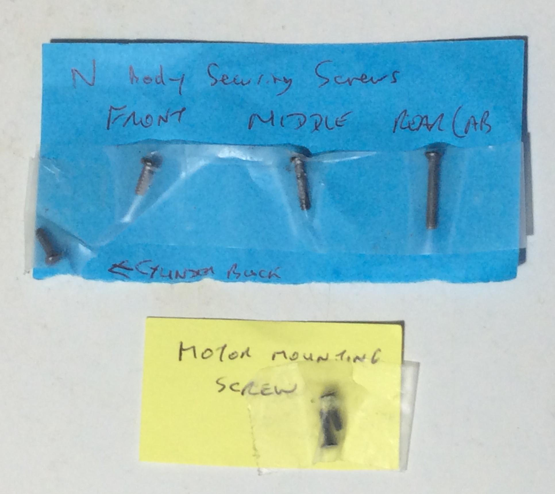
Disconnect the tender. The second item to be dismantled is the pony truck. I placed all the bits from this in a separate bag. Tim Shackleton suggests replacing this pony truck. I disagree; it is a fair representation of the real thing.
Take care dismantling the centre drivers. Do not lose the spring. It should be held in place by Bachmann grease against its cast saddle but it might ping off into the Milky Way. Put both in a bag for safe-keeping.
I recommend dismantling the delicate cylinder-valve-gear assembly from the chassis block or it will probably get damaged (like mine!). The motion bracket is glued in place so needs to be carefully levered out; expect to lose at least one of the plastic retaining pins as you do so. Whilst handling this assembly, try not to push the conn rods or the slidebars inwards; grip the cylinders for preference. Otherwise the conn rods are likely to pop out of the crossheads and the slidebars out of their guides. Check you did not damage anything on dismantling and put it in a box or somewhere safe from crushing or other damage.
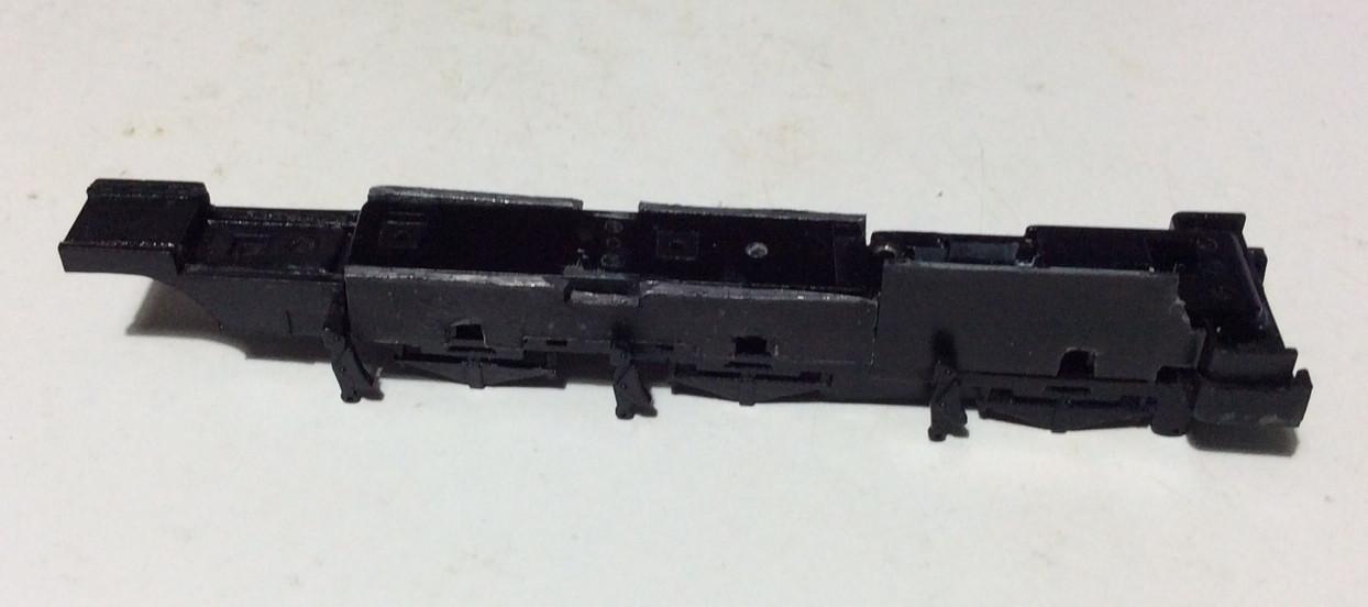
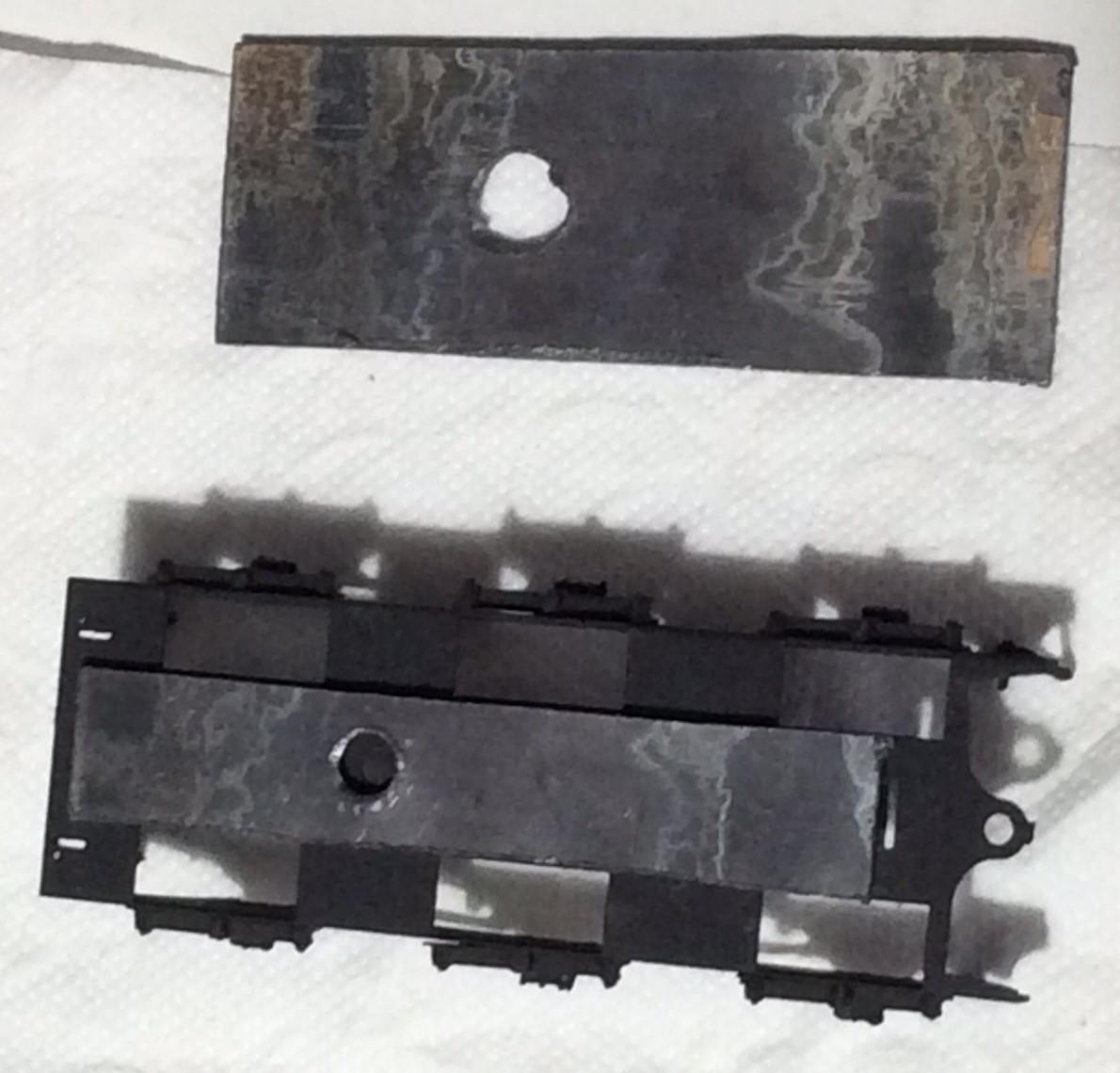
I widened the keeper plate with strips of 0.9mm (1mm should be OK) thick plasticard as per the EMGS Manual. Do not replace the pick-ups until later, once you know you have a free-running chassis.
Widened keeper plate
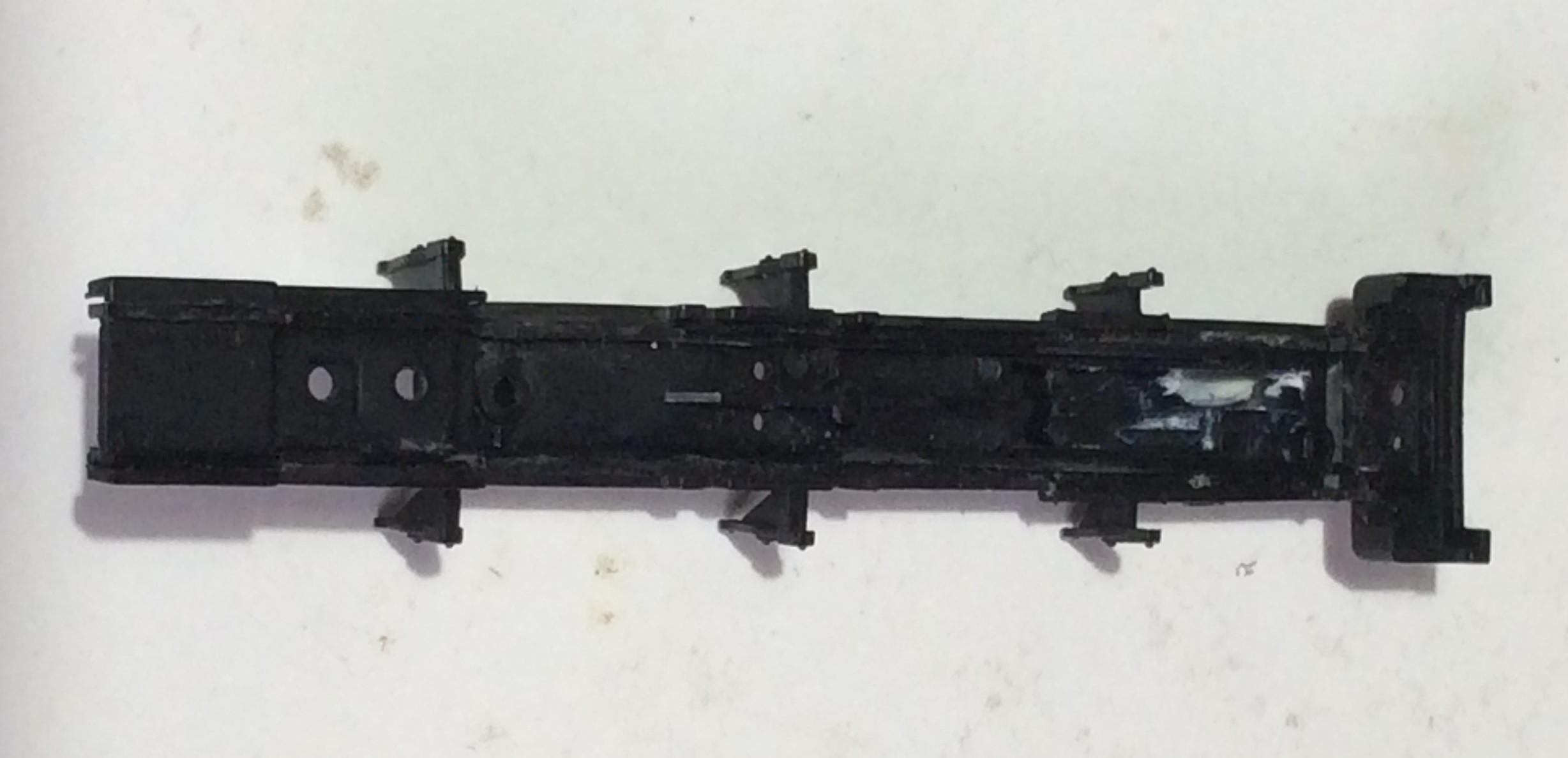
I spent a lot of time widening out the frames cosmetically. I used 1.5mm lead flashing 53mm long for the front part as I thought I might add some weight as recommended by Keith Norgrove. Cutting this to profile with a Stanley knife was fraught as the lead distorted with each cut so the profile no longer fitted without bending. I resorted to a razor saw instead with much easier results but am unconvinced that it is worthwhile; the Bachmann loco is heavy enough already. When profiling to suit, leave a 0.5mm or so margin around the axle holes. The lead flashing was superglued to the chassis block and trimmed back to ensure the widened keeper plate fits neatly. Do not be tempted to file the axle profile in situ; you will damage the Mazak axle bearings. Paint before refitting the wheels. Black 1.5mm plasticard is much easier and quicker to cut to shape, and should not need painting.
The rear frame, which is not so narrow as the front, can be widened with 0.9mm black plasticard 12x 28mm; much easier to profile. If you are planning to re-use Bachmann’s original Buhler motor, I recommend not bothering with this; there is not enough clearance. The rear plasticard sections fit behind the fake (but too solid to remove!) Bachmann firebox bracket and can be left loose; they are retained by the bracket, the keeper plate and the thicker front frame addition. This allows the plasticard to flex around the motor or be removed so there is no obstruction for motor fitting and removal.
Frame widened at front with glued lead, at rear with loose 0.9mm plasticard. If using thicker plasticard at the front instead of lead, you could increase the height to match the rear. As I subsequently decided to re-use the original Bachmann motor, I dispensed with the rear widening; I guess you could use 0.5mm thick plasticard but it will be a very tight fit and thin card is likely to slip or ping out of position.
I filed the overlength 3mm axles down to 22.4mm for the Stanier bevelled wheels. This allows a 16.7mm Back-To-Back with a 0.1mm protrusion of the axles from the wheels at each side. You might want to reduce (to 22.2mm or 22.3mm) for a standard 16.5mm BTB, especially if you are using the GW press-jig (read below).
The new axle for the rear driver needs to be carefully marked for the position of the gear wheel; check it against the chassis block. Do not twist the gear off the Bachmann axle, slide it off; the axle is knurled so it will cut a bigger bore hole in the gear if twisted. I put the axle on top of a vice with the gear wheel resting on top and the jaws open; a tap with a hammer pushes the axle out. I recommend marking just outside where the gear is to be located on the axle. Then abrade the new AG axle where the gear wheel will go. The best way to do this is to take the end of a big coarse file and roll the axle with it up and down a cutting mat. Try not to wander too much using the lines you marked to help; you do not want to affect the axles where it meets the Mazak chassis bearings. Slide the gear-wheel into place. Check the axle in place in the chassis block and adjust so that the gear meshes properly and the axle protrudes equally either side. Then apply a small bit of thin liquid superglue or Loctite 603 to the gearwheel bore either side; capillary action should draw this inside the gearwheel.
Depending on your choice of wheels, you may have to make a hole in the wheel cranks. If so, use a 0.85mm drill, ensuring it is at 90 ̊ to the wheel. Countersink the crankpin holes in the rears of the wheels with a 2mm or 2.5mm drill. Then screw in the crankpins from the rear, remembering that those for the centre drivers are 8mm long. The crankpins should cut their own thread as you screw them in. Make sure the heads do not protrude from the backs of the wheels. Then back them out a little to apply a small blob of glue to the countersink and screw back in. Check that the crankpins are at 90 ̊ to the wheel. Even when AG provide a moulded-in hole (and a counter-sink has been drilled at the back), I find the pins are often at around 100 ̊ to the wheel. I bend them carefully back in one direction only, making sure the bend is at the wheel. Do not worry about being too precise; the crankpin bush and the coupling rod clearances should cope with a small angle irregularity
Omit spacers on the middle driving axles if you want the N to go through tight curves. Allow only the minimum of side-play on the front axle as per the EMGS Manual. This maintains clearances for the valve gear and crossheads. I allowed too much sideplay initially and discovered the crankpin was catching on the conn rod. Adding washers, I ended up with a clearance of almost zero so the wheels were a bit tight against the chassis. This is preferable to the motion locking up and will ease slightly after running in. I had trouble getting the spacers right. I ended up with EMGS 3mm brass spacers fitting against the frames and Peco fibre washers against the wheels; these have the advantage that if you cut a small slice out of them you can add or subtract them from the axle to suit, without dismantling the wheels from the axle. These fibre washers can also be thinned slightly with a fine file if necessary. Side-play on the rear axle is restricted by the final gear wheel so I omitted any spacers for that.
If you use the GW jig/press, you are advised to cut out the wheel boss shapes from 2 pieces of card which should then support the tyres in the press. Otherwise you will probably (100% in my case) end up with wobbly wheels. This is essential for the Crab wheel whose boss protrudes c0.45mm above the tyre; most cereal box card is about this width. Test the wheel in the jig with the tyre support card/paper/tape in place; if it can wobble, the support is probably not thick enough.
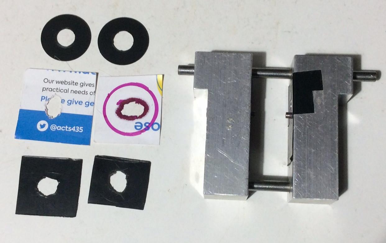
Tyre support cut-outs of various thicknesses and sizes for GW quartering jig.
Another tip for success is to gently twiddle a 4mm drill in the back of the wheel, but only once around; we want to help the axle locate in the wheel without reducing the wheel to axle surface area interface (sorry I cannot conjure a simpler wording!); we do not want a loose axle. A drop of water in the wheel hole can also help the axle to locate properly.
Check the wheels with crankpins can now lie flat in the GW jig. The centre drivers with long crankpins will not; read below.
Do not forget to have your Back-to-Back gauge between the wheels as you use the GW jig. I use a 16.7mm BTB gauge and press tightly onto it. I am happy if the result is between 16.5mm and 16.7mm. I find that AG wheels often spring back a bit due to the plastic centres, so I end up with an average of 16.6mm. If you use a standard EMGS BTB 16.5mm gauge, you should aim for a sliding fit (just). If you are worried about this, GW Models make an adjustable BTB gauge for £15.00; I find it useful to have BTB gauges set for my upper and lower limits. Once you have assembled the wheels, check for wobbliness regardless of the previous precautions. If there is a slight wobble, as I seem to get, try leaving the wheel set in a tight BTB gauge for 24 hours. Do this immediately so the plastic centres deform to the desired position (I have tried leaving them for a further 48 hours on a radiator but this was unsuccessful). This is another reason to have an adjustable BTB gauge. If your wobble is serious e.g. the wheels hit the frames once per revolution, then I am afraid you need to buy new wheels. Do not fret; this happens to me a lot (including the centre drivers on this N)! The worst thing you can do is to persist with a wobbly wheel-set. Not only does it look awful but it guarantees troublesome running, especially at low speed. How do I know……..?
Adjustable GW BTB gauge and wheelset in fixed 16.7mm gauge in a dewobble attempt.
The centre drivers have 8 mm long crankpins which are too long to fit in the GW quartering jig. I tried using a 2mm thick tyre support to overcome this. This gave difficulty in ensuring the jig’s axle insert still protruded from it enough to hold the wheel in position. Sure enough, I ended up with a wobbly wheel….
So the second time (with new wheels) I quartered these wheels by eye, sighting through the spokes and checking the opposite side with a mirror. They were carefully clamped together in a vice with a BTB gauge between.
I use Japanese compass cutters, made by Olfa of Osaka, to cut out the balance weights from black 0.5mm plasticard.
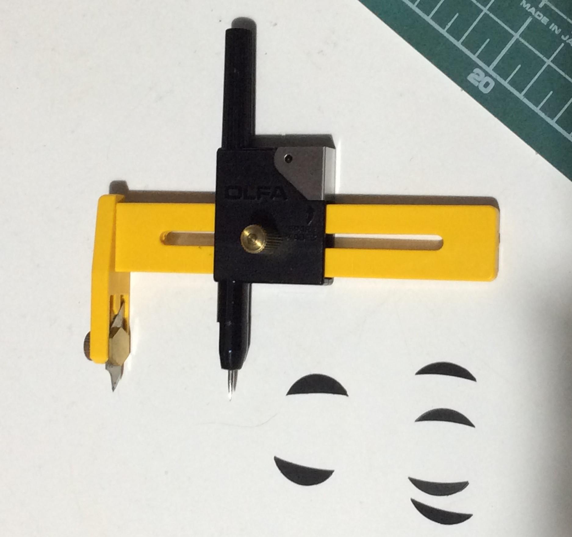
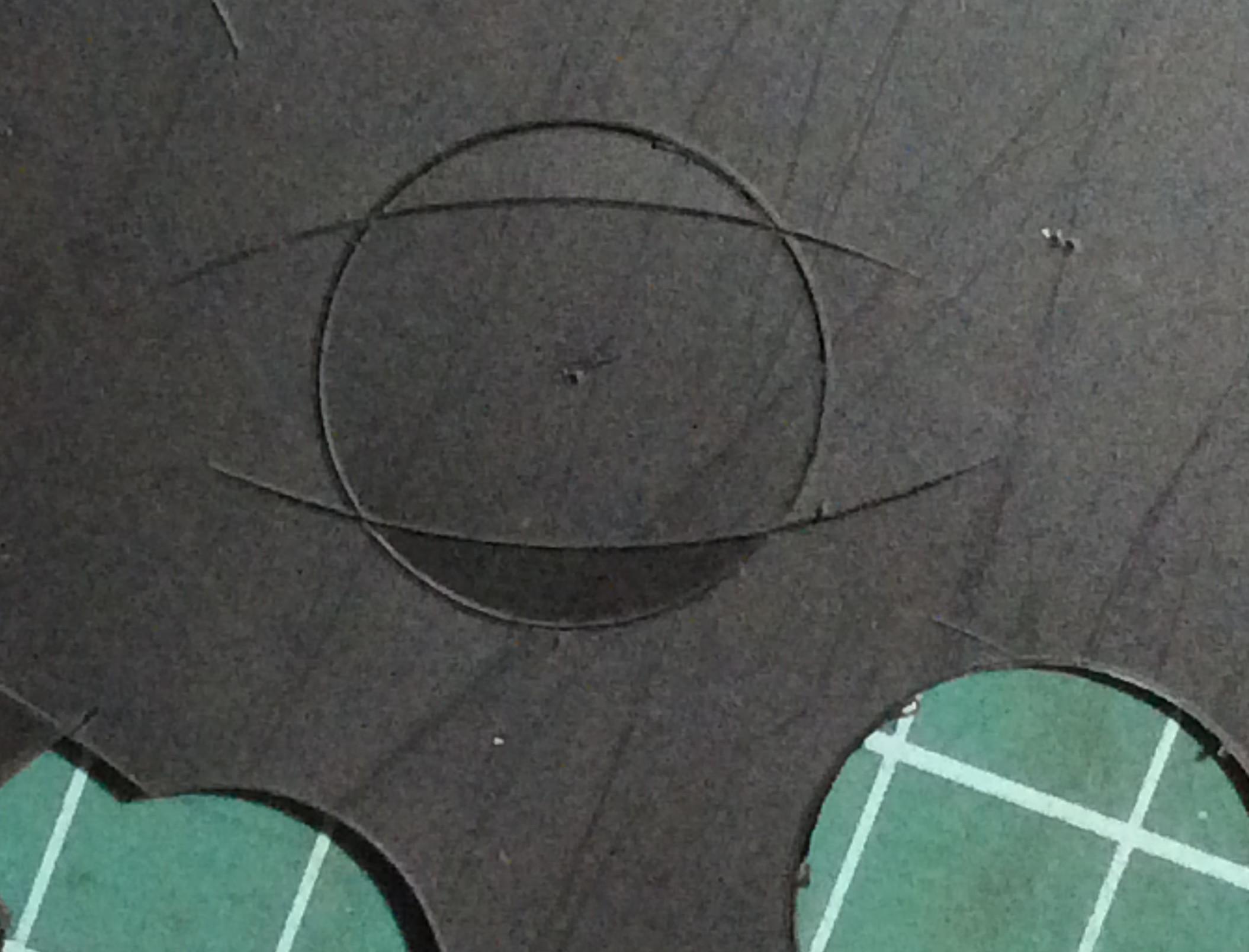
I cut discs of 9.5mm radius to fit inside the tyres. The discs were not fully cut through the sheet. This allows one to cut the large radius curves (I used 30mm) on the inner side of the balance weights before breaking them out of the sheet.
The Bachmann weights on the outer axles look a bit thin to me; I increased the width by 0.5mm. I always cut double the number of discs I need, as I have trouble marking out black plasticard accurately, so as to be able to select the 6 best looking weights from a large sample. Now you have to decide whether the balance weights are handed or not; look up your prototype photo if this concerns you. I took the easy way out and copied Tim Shackleton; his N appears to have the weights placed symmetrically about the crank; this makes it much easier to position them on the wheels. I mark the tyres with a black marker pen where the ends of the weights should be. The weights were fixed to the spokes with small dabs of glue. Epoxy resin gives you time to position the weights inside the tyres but is messy to use. Superglue is cleaner but allows no time for repositioning. Either way I seem to end up with sticky fingers. Make sure they do not protrude too much from the tyre or they are bound to catch something! I clamp them in place using aluminium hair grips until the glue cures.
I found fitting the balance weights to the Stanier wheels more awkward than normal, something to do with the flare of the spokes, I guess. Using a finger to dish the balance weight on the centre driver helps to fit it. Be prepared to sand them down.
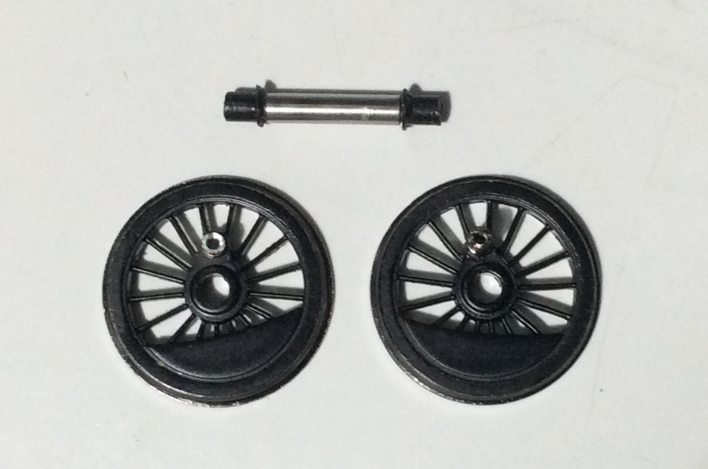
Completed Stanier bevelled wheel set. Note offset gear wheel, Peco fibre washer and longer crankpin on the centre driver.
Now fit the sprung saddle to the chassis block and lightly grease this and the axle bearing points (I use a Teflon-based grease). Insert the drivers and secure the keeper plate using the centre screw. For location it might help to fit the rearmost screw as well but you probably need a spot of BluTack to stop it falling out. Make sure the centre drivers flex i.e. that the spring works; the cast saddle is easily displaced on re-assembly. Do not fit the motor or coupling rods yet. Also defer re-fitting the pick-ups. Road-test the chassis to ensure it runs freely; but do not expect it to run as freely, for example under gravity, as a chassis running in brass bearings or fully sprung.
The centre driver coupling rod holes should be left at 2.1mm diameter as per the original but the others need closing up. I followed Pete Hill’s excellent advice. Abrade the back of the Bachmann rods at the crankpin holes to remove the plating and give a surface for soldering. The AG conversion bushes (code 4800) should be a good tight fit in the holes. If they ping out or refuse to lie flat, open up the hole from the back with a gentle turn of a taper cutting broach. You do not want to remove too much metal so retry before opening up the hole further. If you use a RSU to solder be careful you have it on a low setting or the castings could disintegrate. You will probably need to open up these bushes a little once you have soldered them in place. I always have to drill them anyway as I end up with blobs of solder blocking the holes. The drill should find the soft hole centre naturally. It is best to drill them 1.5mm only and then open up the holes slightly with a taper broach; you want running clearance only. If the fit is too tight the bearing will end up being the crankpin thread. Test the holes by fitting with an AG crankpin bush; with gravity it should fall out -just, maybe with a gentle tap. If you plan to use ordinary bearings with the front axle crankpins, then you need to also close up the coupling rods there, as above. If, as recommended by the EMGS Manual, you intend to use AG axle nuts back to back as a bearing on the front crankpins, then you will have to open them out to 1.9mm diameter; the nuts have a diameter of just over 1.8mm.
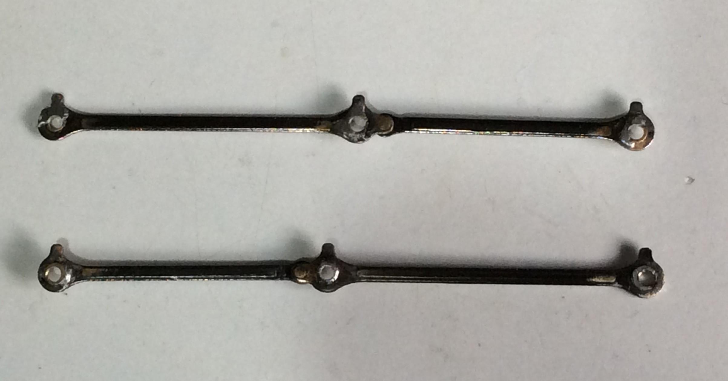
Rears of coupling rods with brass bearings (AG 4800 bushes) inserted. The holes for the front drivers need to be opened out. I later removed the centre rod bushes to enable a 2mm crankpin bush to be used for both the coupling rod and the connecting rod.
Now cut 2 lengths of 2mm o/d 1mm i/d brass tube 2.8-3.0 mm long. Do not use Xuron cutters or similar; cut with a saw. Try not to scratch the outside surface and file the ends to length. Put a 14BA or M1 washer over the centre driver crankpin, followed by this bush (M1 washers 0.3mm thick can be obtained from Prime-Miniatures on eBay). You can use (AG short) 1.4mm bushes for the rear axle. The front axle should not have bushes but a crankpin nut screwed in. Another one will be inverted and be screwed inside the rod to form an effective 1.8mm diameter bearing for the coupling rod. Do not reuse old crankpin nuts for this, only brand new ones. Old ones that have dropped off or been screwed on and off are likely to have scars that might affect smooth running. I filed about 0.1mm off the face of the inner axle nut to reduce its width to try and prevent clearance issues later. Cut 1.5-2mm or so length of electric wire with a core diameter of approximately 2mm diameter (12AWG) and remove the core. You need 2 of these bits of insulation to replicate the conn rod big end being in place. Fit the crankpin bushes, coupling rods and crankpin nuts (temporarily, including the centre drivers) with the insulation between the coupling rod and crankpin nut on the centre drivers. Now road-test the chassis again but with the coupling rods. If the chassis runs smoothly but is tight with no jerkiness in each revolution, that is probably OK; the chassis just needs running in.
Note that if you use 1.5mm o/d tube for the centre driver bushes (the AG steel bushes are too short), you will have to solder or glue reducing bearings e.g. AG 4800 bushes to the insides of the conn rod holes. I found soldering these to be extremely difficult due to the mass of the conn rod big end. Upping the temperature resulted in the rod disintegrating; Ugh! Using 2mm o/d tube for the crankpin bushes avoids this and saves adding bushes to the coupling rods.
If the motion is not smooth per revolution, first check for any possible obstruction of the rods. The usual culprits are axle ends protruding too far out of the wheel (file them down carefully), the wheel balance weights, often sticking out at one end (smooth them down with a fine file), or the backs of the coupling rods not being flat (more filing). Otherwise it means there is a quartering problem or the bearings soldered in the coupling rods are not centred (probably fitted too loose or too tight). If the coupling rod bearings are not centred in their holes, it is often possible to see this and to replace the bearing so it centres (recommended) or to widen the offending hole. You could try measuring centre to centres of the axle holes for discrepancies (they should be 29mm and 33mm) but doing this accurately is fraught with difficulty. Note the coupling rods themselves should not be at fault if they ran OK in OO.
Otherwise the issue is with quartering, likely a result of not using the GW jig throughout. First you need a test track that is flat and firm with no dips or peaks (which rules out most of my layout!) and is straight (but a gentle curve is OK). Gently push the chassis along from the end without pressure from above. If it seizes, place a mirror behind the loco and compare the coupling rods. One set should be perfectly horizontal. The other is likely to not to be so. Wherever the offending rod is out of alignment indicates where the coupling rod hole needs to be opened out slightly. This may not be too obvious. So move the chassis along so that the perfectly aligned rods are at Bottom Dead Centre. This means the other rods should not only be horizontal but in line with the axle centres so a little easier to discern where there is a misalignment.
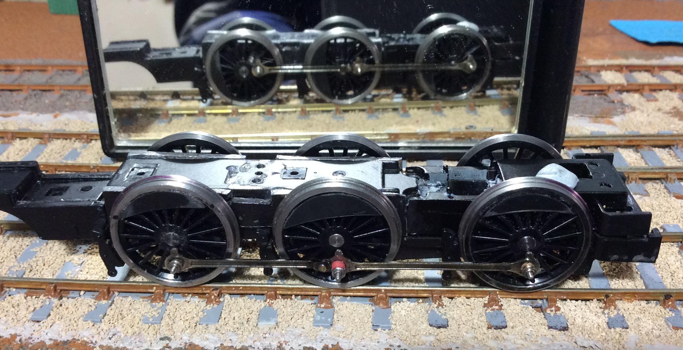
My chassis with facing rods at Bottom Dead Centre showing the opposite rods in the mirror with a slight peak on the centre driver. This hole needs opening out a bit to relieve a slight jerkiness. Not surprising really as the centre driver quartering was done by eye. This was confirmed by running the chassis up and down a test track a lot (but this time exerting some pressure from above), whereupon the crankpin nut in that position duly came undone. As it is the centre driver that seems out of alignment, the rod holes on that driver and the undriven (front) driver should be opened up slightly. Avoid opening up the rear drivers (i.e. those with the gears) if possible.
If after this the chassis seizes or jerks in the same spot, open up the opposite holes slightly in the other coupling rod.
If you still have trouble tracking the source of the problem down, try disconnecting the front driver from a coupling rod, one at a time. If the rear and centre drivers now run smoothly coupled together, you know it is one of the front coupling rod holes that needs to be opened up. Conversely if the 4-coupled chassis still runs as poorly as before, you now know the centre and/or rear drivers have an issue.
You can repeat this trick with the front and centre drivers running as a four-couple chassis. But ensure the rods stay horizontal as you do this because the joint in the rods will allow them to flex (=great fun!).
Another clue is the crankpin nut falling out from the chassis as you run it up and down the test track. That usually tells you where the rod needs to be opened up.
If the above fails, try slightly opening out the coupling rod holes for the centre drivers only; one turn only of a taper broach from the back of the rod. Try running as a 4-coupled only unit, as above. Then if needed, open out the front driver coupling rod holes slightly. Check again. Only then should you open out the motor-driven rear driver holes slightly. The last thing we want is to replicate the worn-out clanking of motion badly needing a full works overhaul. If you overdo this, the remedy is to fill the coupling rod holes with solder and then drill them 1.5mm or as appropriate. Try them on the chassis again.
Now you have a smooth-running chassis, dismantle it. I ditched the suppression unit screwed to the motor saddle and replaced it with a plain strip-board to which I can also attach power leads from the tender. There is a plastic pin in the centre of the saddle. If you open up a hole in the strip-board to 2mm to take this, you will hopefully find that the strip board aligns with this and a screw-hole 2 holes away. Open up that hole with a 1.7mm drill and you will discover the strip-board, once cut to shape, sits comfortably on the back of the saddle. Re-use one of the original screws to secure.
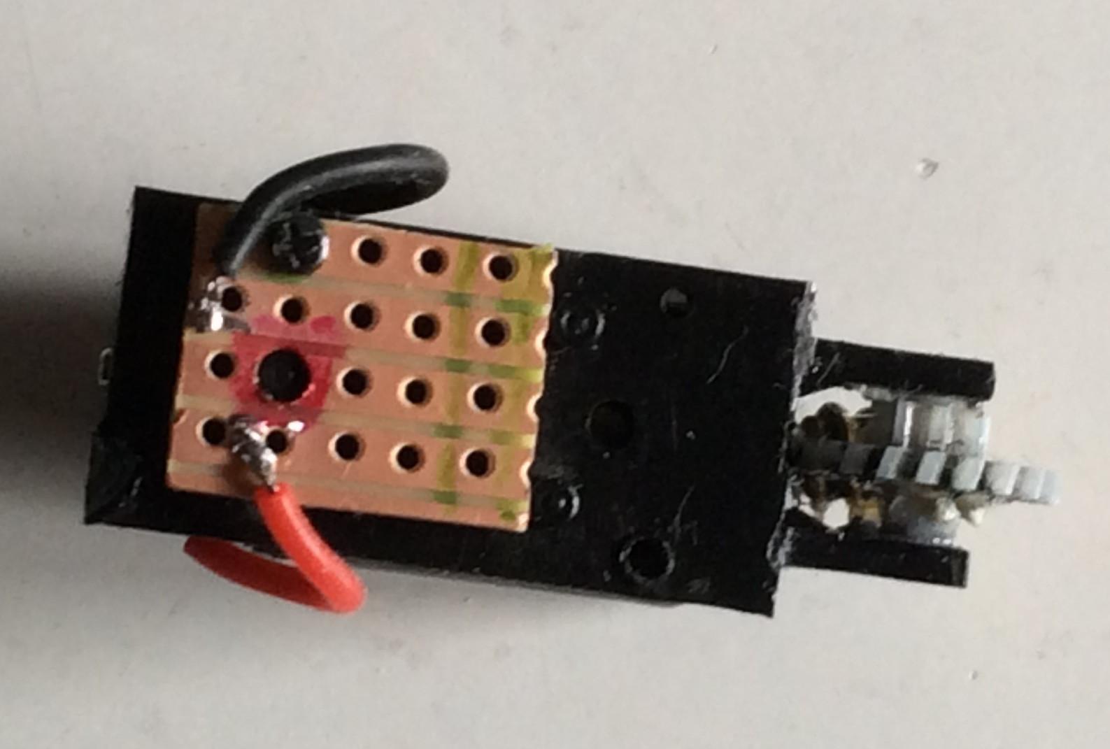
Plastic pin location highlighted in red. The strip-board is bigger than necessary because I like to play safe if possible and leave an unused strip between the 2 live ones to help prevent potential shorts.
If you copy this, wire up the motor to this board and check the motor runs smoothly i.e. that there is no poor connection or short. Replace the motor and saddle and fit the motor mounting screws to hold it in place. Refit the pick-ups and rewire to the motor. Glue the pick-up assemblies in place if too loose. Lightly re-grease the gears, and the axle bearings and centre axle spring assembly if necessary. Refit the keeper plate as before. Test under power. Any jerkiness is likely to be the pick-ups catching something or being out of alignment. Another possibility is a lump of dirt or swarf caught in the gears. Yet another is a poor power connection (loose or shorting) from the pick-ups. Dismantle and correct if you have to. Note that the rear axle may oscillate if the keeper plate is loosely fitted to the chassis block and may induce poor running; a blob of Blutak on top of the rear fixing screw helps to control that.
Unless you have replaced the Bachmann coupling rods with fine-scale ones, do not file down the Bachmann connecting rod to reduce the width as per the EMGS Manual. If you do that, you will discover that the large coupling rod rivet fouls the conn rod (see diagram below). Cut off the rivets joining the Bachmann crank to the eccentric rod without damaging the rod; I used old Xuron cutters.
Now the AG crank needs to be tapped M1. It is easier to do this whilst the castings are still on the sprue. Drill the hole 0.85mm making sure it is at 90 ̊. Whilst doing this, drill the hole at t’other end of the crank 0.85mm as well to take a rivet. Now insert the tap into the big end hole and cut into the brass gently. If the tap becomes tight, withdraw the tap and repeat. Do not rush or overtighten or you will break the tap. You need a piercing saw to cut the castings off the sprue, then clean the cut off with a file. Now you must put a double crank in the cast crank!
Double cranks bent in the cast AG eccentric crank. I must be getting quite cranky…
This is needed so the crank clears the (cranked!) connecting rod and also so its big end (the crankpin) passes under the eccentric rod:
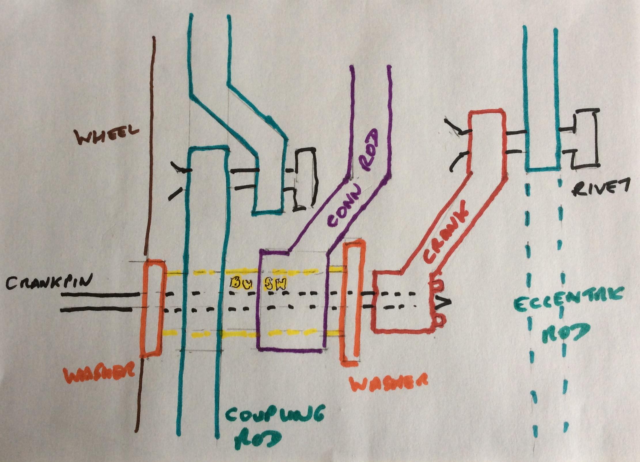
Diagram showing clearances congestion on centre driver crankpin and the avoiding cranks. All due to Bachmann putting a crank in the coupling rod for an oversize rivet. Definitely not to scale!
Now rivet the eccentric rods to the little ends of the cast cranks. Be careful you do not inadvertently damage anything in this process. Insert a rivet into the eccentric rod from the outside face. Place on a flat metal plate or similar. Now place the little end of the cast crank over the rivet so it projects through the crank hole; ensure the crank rivet detail faces outwards. Hit the rivet gently with a lump of hard metal, a small hammer or best of all, an engineer’s centre punch.
This will make the rivet splay out and secure it. You will need to hit the rivet a few times. Test: gently start to lift the crank away from the eccentric rod. If the rod does not come with it, you need to hit the rivet again until it splays. Try not to over-hit the rivet or the joint could end up too tight. If it is tight, loosen by repeatedly turning the crank. Loose but secure is OK. Now is a good time to paint the brass crank. I used Humbrol gun metal enamel.
Note that if the conn rod little end falls off the assembly (one of mine did!), the crosshead has a rivet-type arrangement of soft metal (which is why it falls off easily!). If you force the conn rod into place back over this, you can then hit this with a centre punch to re-secure the rod. The valve gear must be off the chassis as you need a metal plate under the rivet.
Before replacing the cylinders and valve gear, cut the crankpins on the front drivers to length, filing the ends smooth (or the crankpins will foul the crosshead). Then the valve gear assembly can be fixed back in place on the chassis and the conn rod added to the centre drivers. Do not fasten the motion bracket down permanently yet; you may need to flex it.
Prior to adding the crank, add a thin washer to the end of the centre driver crankpin. This needs to be at least 2.7mm, if not 3mm, diameter so as to stop the conn rod from wandering out and hitting the crank. I used ancient Romford crankpin washers (3.2mm dia) but an M1 or 14BA one might do. Make sure there is at least 1.3mm of crankpin protruding after this washer (there should be) so there is enough thread for the crank; if not, use thinner washers; do not shorten the bush to less than 2.8mm or the clearances between the coupling and con rods may be too tight. Wind the tapped crank down the crankpin of the centre driver until it will go no further. You may have to flex the eccentric rod over the crankpin end to do this (the crankpin will be shortened afterwards). Then reverse it until it is at 20 ̊ and behind the axle when the crankpin is at bottom dead centre (as per the Precision Miniature Arts drawing). I have read (including the DJH kit instructions) that the angle should be only 5 ̊ but photos seem to show a bigger angle. If the crank ends up just short of the desired angle, disassemble and file a tiny bit off the end of the bush (but try to ensure the bush length does not go below 2.8mm; alternatively thin the end washer). You need to disconnect the rear driver from the coupling rods as the worm-gear will not allow you to turn the drivers. I discovered that the best position to wind the crank on is when the wheel is near Bottom Dead Centre. You may find you need to turn the wheels a little to wind the crank down. With the crank off, add a little Loctite 603 to the end of the crankpin, enough to just to run in the thread but no more because you do not want it to run over the crankpin bush and seize up the conn rod (note it will most probably seize up the bush so taking that off the crankpin e.g. to shorten it, might be difficult later). Use a cocktail stick, toothpick or pin to control this. Then rewind the crank back on. If you are happy, wipe another spot of Loctite 603 onto the crankpin end so capillary action will take it along the thread. Allow the 603 to cure overnight.
Cut or file off any excess crankpin so it clears the eccentric rod. Note there is no protrusion on the real thing but if you file the crankpin down too much you will damage the rivet detail on the crank (you cannot win!). Take care you do not dislodge the crank from its angle (if you do, reapply 603 as above). Cut off the excess crankpin from the rear drivers. Touch up any blackening or paintwork required. Make sure the slide-bars are not bent or out of position (mine were and in correcting that, the conn rod duly fell off the crosshead!).
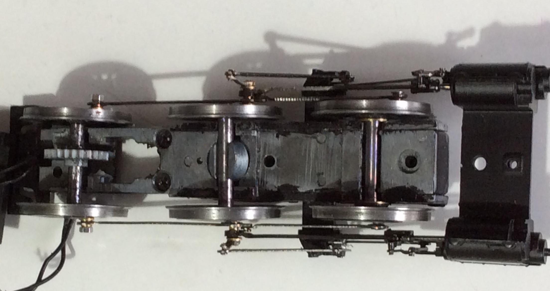
Note how the replacement cranks are only just within the loading gauge (hopefully!). Also note the sprung saddle is dislocated; it must be positioned so the pin is vertical and can move up and down freely. Bachmann put a heavy blob of grease over the spring and pin to try and keep them in place; I will do the same.
Now disconnect the coupling rods from the rear drivers so the front coupled wheels can turn. Slowly turn the wheels and check that the motion does not catch or knock anything. Now check again, but this time gently flexing the rods and wheels to see if it is possible for unwanted contact to be made. Repeat in reverse. Doing this I found I had allowed too much side-play on the front axle (corrected by inserting Peco fibre washers; see earlier picture above).
Test the loco under power one last time. If there are any problems you now know that they are with the cylinder/valve gear assembly somewhere. If all is OK, fasten the cylinders with the retaining screw; if this is a replacement cylinder set, expect to use some force to cut a thread in the block; Bachmann use a machine tool. Bachmann glue the crosshead support in position. I used a little Black Tack to hold it in place until the chassis block is fixed to the loco body; then the plastic pins and the body secure it. If you glue it permanently, the pins will break off if you have to ever remove it.
When reassembling the body to the chassis, be careful that the electric cables are not snagged, especially in the corner of the hole adjacent to the retaining screw. Also check that in handling you have not inadvertently dislodged the crank from its 20 ̊ position; I managed to do so.
If the loco is running up to your expectation, remove the crankpin nuts, apply some threadlocker (not 603 or you could have trouble removing them later) and replace, to stop them falling off. In theory this should not be required if the chassis runs smoothly. But I live in the Land of Murphy and Sod supervises the Law. If you know you will re-use the Bachmann drawbar, you may want to fit this to the loco now whilst the keeper plate is off, but you can safely defer this until after the tender is converted.
The Bachmann pony truck can be reused, along with its top-acting spring. Unmodified this gives a massive 5mm side-play for the wheels which is most undesirable, especially if you want to use couplings like AJs that need to be centred. I used 2mm axle bearings to take up most of the slack, leaving only 0.3mm side-play. If you are fussy you could instead construct and install the springs and hornguides that take up the slack on the real thing (but will anyone see them?).
On my first N conversion I was anxious to maximise the possible pick-up points so the pony truck has them. The wheels have EMGS shorting strips and the axle is split. Another set of shorting strips is used to connect the axle to side control springs on the pony truck frames. In turn these are slid into handrail knobs on the underside of the keeper plate which are connected to the main pick-ups. Hmmm…..
In hindsight, picking up from the pony truck is not worth the hassle. Connecting the knobs to the main pick-ups and drilling through the shorting strips at an extremely acute angle (refer below) were extremely troublesome jobs. The transformative way to improve current collection is to add pick-ups to the tender; put your efforts there. I confess it is doubtful that my old N picks up current from the pony truck; the extra pick-ups from the tender are so reliable it is not worthwhile worrying.
However, I do believe that fitting side control springs is desirable if the pony truck has an AJ coupling or similar requiring centreing (if the coupling type has a loop, like Dinghams or Sprat & Winkles, this is not needed). This is comparatively easy. The tricky part is drilling an acute angle in the side of the rear frame with a 0.3mm drill to take a guitar spring. This hole needs to be level with the frame and as near as parallel to the wheels as is possible. Fortunately there is a mould line on the outside of the frame which acts as a guide and helps stop the drill from drifting initially. The secret is to drill at 90 ̊ to the frame for a half millimetre only. Then using that hole as a starter, drill at as an acute angle as you can. As you drill in you should be able to gently flex the drill towards parallel. Do not be surprised if you break the drill. Next cut 2 pieces of 50mm length of 11thou (=11 gauge) guitar string and thread them through the frames. Secure with a dab of superglue gel on the inside of the frame.

Guitar spring wire glued into the pony truck frames. Note the thick 2mm bushes needed to eliminate excessive side-play. The wires will end up being pressed against the loco keeper plate springs. If this action is too strong, the wires could be replaced with a thinner gauge.
Thread a handrail knob onto a spare bit of guitar wire. There are 2 holes in the keeper plate next to the central keeper-plate-to-chassis securing screw. Note that if you have reinstated the Bachmann pick-ups complete with rivets, these holes may not be available; in that case drill some holes 3mm or so further aft. Place a drop of superglue gel over one of the holes. Now add the knob plus wire to the hole with tweezers, keeping the wire parallel to the loco frames. Once in position, withdraw the wire leaving the knob in place. Repeat for the other side. Allow the glue to cure.
You could add small metal tabs to widen and lengthen the guard irons but I suspect they will soon get knocked off unless they are pinned as well as glued. I discarded the tension-lock coupling and cut a 9mm long piece of 6mmx6mm brass angle to go in its place. The upper part was drilled 0.3mm so as to provide an anchor point for an AJ coupling. By drilling a 2mm hole at the bottom, the original screw can be re-used to hold the new coupling in place.
The completed pony truck needs to be assembled to the keeper plate. You must hold the truck, Bachmann (top-acting) spring and retaining screw together whilst threading the two spring wires through the handrail knobs on the keeper plate. This can be a bit fiddly (try threading one first then the other at an angle; use tweezers). The keeper plate frames will act to keep the springs from straying. Once everything is in position and screwed down, check the wire springs centre the pony truck. You may discover that the wire springs catch on the ends of the keeper plate frames; file the ends down to slope at c45 ̊ so they no longer catch.
Pony truck centred with springs in knobs.
Against expectation, the Bachmann loco brake rods fitted in place comfortably despite the widening of the keeper plate.
One of the remaining jobs is to fit a fall-plate. The shape of this will be determined by the tender option. Also the drawbar needs to be sorted out beforehand. Leave until the tender is finished. You will find that the drawbar can be pushed into the loco with just the rear and middle body retaining screws eased out slightly; the keeper plate does not need to be taken off. Make sure the fall-plate allows the loco to negotiate curves; it will be necessary to round some of the corners of the plate.
Likewise be wary of fitting cab doors. If you fit them closed, the ability of the loco to negotiate tight curves will be restricted. I could not be bothered; few photos show the N with the cab doors closed.
PART THREE: CONVERTING THE 3,500 GALLON TENDER USING THE MT KIT
For a straightforward conversion I used the Mainly Trains frames for a 3,500 gallon tender.
I am fortunate in having the old version of the MT kit which included axle-boxes with springs. Before doing anything else, cut out a template of the main chassis floor so that an extra (almost duplicate) floor can be added to the sub-chassis -refer below. I recommend lengthening the slots at the rear of the main chassis to carry the guard irons; this means cutting to the edge of the outer frame. Otherwise, like me, you will probably have problems with them fouling the brakes (see below). The prototype drawings show the guard irons to be hard up against the buffer beam; Mr Rice has set them at least 1mm too far forward. Use the inner slots for EM.
Assembly is relatively straightforward. Use a straight edge to bend up the frames or, like me, you will end up with a distorted chassis. This is especially the case with the inner sub-chassis which resists folding to 90 ̊; widening the fold line slightly with a triangular file might help. Note the tab to locate the Mainly Trains inner tender sub-frame to the outer, is etched on the wrong side. Be careful you do not automatically bend it down instead of up! Do not make the mistake of permanently fixing the inner frame to the outer, otherwise you will not be able to insert or take out the wheels. The other tab, which correctly bends down, is an anchor point for an AJ coupling. Fix the guard irons so they butt up against the edge of the buffer beam and fill the unused bit of hole with solder so they do not bend back after any impact with stray cows etc.
The Iain Rice drawing for the Mainly Trains tender chassis kit incorrectly shows the brake stirrup outside the tender frame; to align with the brake standard on the tender floor it has to be inside the frame. The actuating crank should be outside as shown so a small wire rod should connect the two. As this is not very visible, I dodged this fiddly bit of soldering by double-cranking the crank so one end is outside the frame and t’other inside. Then the stirrup can just be soldered directly to the crank.
Double bend in crank for brake stirrup. Yet more cranks!
The kit is designed for the axle boxes to be centred on the etched holes in the outer frame. I suggest you centre them 0.5mm below those hole centres as the whole chassis needs to be raised by that amount (with an extra floor) to match the loco height (refer below).
Frames prior to painting. Note the nickel-silver bracket added to the sub-frame to support the front end of the brake rodding; this was removed as being visually too intrusive.
The kit (no instructions) makes no apparent allowance for the supplied brake gear to be separable from the outer frame; it joins the outer frame at the loco end. This means if the lot is soldered up, the inner and cosmetic outer frames are permanently joined (one may as well solder the frames together) and the wheels become impossible to insert or extract. I tried making up a loose brake sub-assembly that could be clipped into the inner sub-frame and be left loose at the forward end; quite a bit of work.
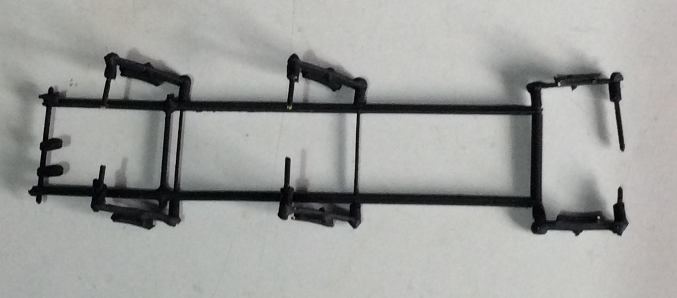
The Mainly Trains brake gear; the spacers are from plastic cable insulation. The front cross shaft could foul the wheels so the protrusions either side of the pull-rods were cut off.
Unfortunately this did not work out for me initially. The rear brakes fouled the guard irons and seized the rear wheels. I tried fitting AG plastic GER brakes loosely and the same thing happened. The problem was resolved by moving the guard-irons rearwards up against the buffer beam as per the prototype; a pain if you do this retrospectively. Then the original brake assembly worked OK (OK but does not look quite right to me).
Spacers were added to the rear axle so side-play is minimal and any coupling is centred. Allow as much side-play as possible for the middle wheels to allow for sharp curves.
The chassis needs to be painted. I used Halfords Bodyshop matt black primer after trying out a non-priming paint which peeled off the cast brass axle-boxes. After painting, the wheels need to be fitted. The hole for the centre axle allows a lot of vertical movement. I added some brass tube to this axle to weigh it down a bit and reduce oscillation. Note it is a loose fit so it does not restrict side-play.
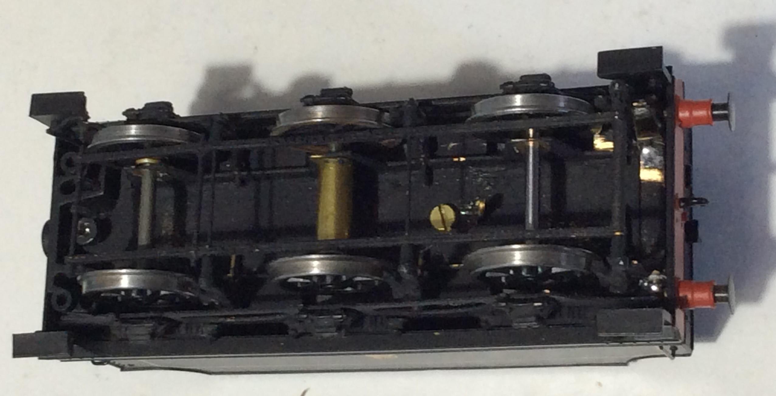
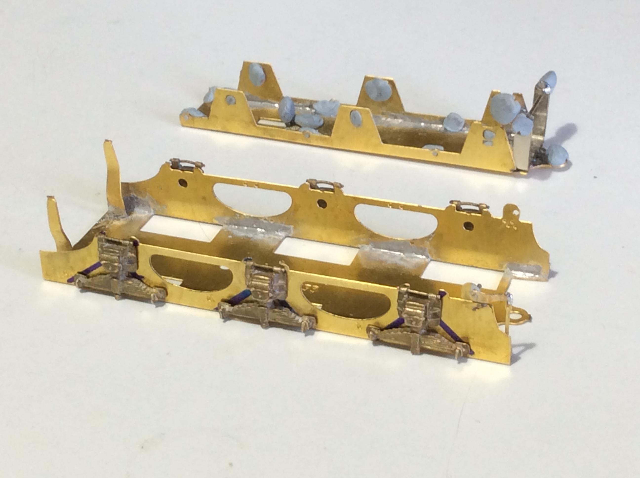
Underside of converted 3,500 gallon tender. Note brass tube on centre axle and AJ coupling tab next to the body retaining screw. Drawbar and retaining bracket still to be fitted.
The unusual Bachmann drawbar arrangement has come in for a lot of criticism. I believe it gets unfairly blamed for all sorts of running problems. I have had no issues on my older N conversion. I think it is a clever design and should be retained. This saves a lot of extra work. Light engine this coupling gives a loco-to-tender gap of only 3.6 mm as per the prototype. Under load this gap extends to 4.5mm due to flexing of the plastic components. Both measurements are for straight track. On curves the gap expands, perhaps disproportionately. For this to be noticeable the radius of the curve has to be tight. A tender loco would not be expected (allowed?) to go through an A-switch turnout so are we bothered?
I replaced the 3 Bachmann tender weights (60g) with 1.5mm thick lead sheets. The first narrow layer was superglued in place but subsequent weights are held only by BluTack or similar; the screw and column joining the chassis and tender hold them in place. Now is a good time to sort out pick-up arrangements from the wheels.
The first layer of lead sheet needs to avoid the wheels. Note the flat lands fore and aft of the wheel apertures which are perfect pivot points for top acting pick-ups
I discovered that the assembled tender was a little too short of height so the footplates did not align. This discrepancy is highlighted by the lining so some 0.5mm thick plasticard 14mm wide was temporarily glued between the main cosmetic frame and the subframe. Although this solved the height issue, the chassis was floppy and one side still did not align properly as a result. The problem is that the sub-chassis does not support the tender and its weight across its whole width. Instead a layer of brass 0.5mm thick was soldered to the sub-chassis using the main chassis floor as a template. As I had a spare MT mainframe (a result of previous failure!), I cut that to suit and soldered it in place on top of the sub-chassis to make a new wider supporting floor, taking care that the screw-holes are aligned. You could use a piece of brass cut to shape or 0.5mm plasticard. Plasticard has the advantages of being easier to cut and glue and acts as a sound barrier but the disadvantage of being not so stiff or strong as brass.
Extra floor added to sub-chassis to increase height and provide better support for the tender body.
This new floor makes the axle boxes look slightly high (if you did not allow for it earlier) but I think this is preferable to the bodies being out of alignment.
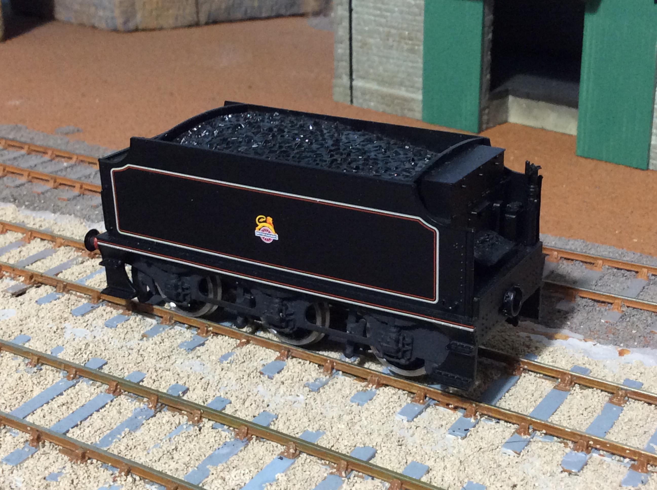
Converted Bachmann 3,500 gallon tender body with Mainly Trains frames. Fire-iron support still to be fitted. Wheel blackening outstanding. The lack of air between the vertical handrail and the body is all too evident and needs to be sorted with carving out and a new brass wire rail. Tender not quite sitting on the track properly so, like a lot of my vehicles, looks like preparing for take-off!
PART FOUR: CONCLUSIONS
I did try and convert a Hornby Schools tender to suit the N but gave up (after a lot of work!) when I realised the bodywork shaping and lining involved. The chassis for this makes for easy conversion and a smoother ride, thanks to the Hornby flexible plastic sub-chassis, than I obtained with the Mainly Trains 3,500 gallon tender. I am not happy about the brakes on the MT tender but this is probably a result of my lousy workmanship; I may yet replace the internal sub-chassis with a Comet one. If you go along that route, why not try split frame current collection (why should I be the only one with wobbly 2mm axles)? Were I to start afresh with either 3,500 or 4,000 gallon tender, I would probably go for widening the original frames and using the Rumney chassis.
I toyed with the idea of replacing the big Bachmann/Buhler motor but I do not think the designed combination with 60:1 gears can be bettered in the space available.
The completed model runs smoothly. However the tender brakes misbehave occasionally so I may overhaul or build a new subframe. The other niggle is the centre drivers do not look quite right to me and this feeling is enhanced by the attention drawn to the valve gear and cranks when in motion, especially when compared to my earlier N. I may end up replacing the Bachmann coupling rods and eliminating a lot of those darned cranks!
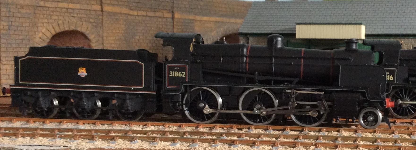
The final loco. The lining on the tender seems too bold; it needs toning down or weathering to disguise it.
The new and old Ns compared:
A lot of cosmetics are outstanding. As they are on the old N. I must upgrade both! The wheels on the newer N are too shiny; I will probably have to use gun blue again to get the same effect as the older loco.
If you want to upgrade the Bachmann model further, then refer to the makeover by the late Iain Rice in his “Realistic Railway Modelling- Steam Locomotives” book (published by Haynes). This includes replacing the odd Bachmann drawbar arrangement, refining the buffer-beam details and fabricating the injectors omitted from older Bachmann models.
I also have a Finecast N chassis half-constructed (for the past 2 decades!). So I guess I will have to stick the DJH body on top (only the boiler barrel is complete) in the next 15 years or so! Hmmm…. Rereading MRJ112 it seems Tim Shackleton thinks the DJH loco ends up being 2mm too high and the footplate is wrong; that might explain why Work-In-Progress ceased an awful long time ago and I converted the Bachmann model! Oh well, I suppose you cannot have too many Ns or spare parts for them, as the Southern Railway realised. On the other hand, do I really need another N? And will I have the time and determination to complete it?
If you are a relative novice proposing to have a go at converting the N then do not be put off by the above ramblings. If I, a ham-fisted non-engineer, can do this (twice!) then so can you. Hopefully these notes will help you find your way and avoid some of the potential pitfalls.
If you are reading this and you are an experienced modeller, then I would urge you to try and write up your next EM conversion on this forum or as a Manual Sheet to help those of us who struggle to match Tim Shackleton and the P4 elite. It takes a lot of effort and time but I found it useful personally. I realise that I should think more about what I am doing or trying to do, the process if you like. And that is what this is, a description of a process. A word of caution, though. The EMGS will try and persuade you to publish as a Manual Sheet. I did that once and it was an interesting and illuminating experience being edited. But Manual space is a constraint so lots will be cut out and because of legal liabilities all sorts of Health & Safety stuff gets inserted. My advice is to prepare a draft with pictures, forget it overnight and then edit the next day. Repeat at least 3 times before posting on the forum or submitting it to the Manual editor! You will be surprised at what you amend or add in order to clarify or complete the description. Remember that clear photos can help explain a lot. If it is not up to standard, expect lots of comments on this forum!
If you are reading this and think you can improve on my ramblings, then please add your expertise (photos please!) to these postings so others (and probably me!) can benefit.
The completion of this second conversion and the write-up is undoubtedly the cue for the release of a new or upgraded model of the N! But will it have finescale wheels easily convertible to EM? Best of all would be if somebody were to produce a 3mm diameter EM axle for the Bachmann N with splined ends; then the excellent Bachmann wheels could be re-used (although it might be wise to file down a bit of flange thickness from the rear of the wheels using a mini-drill). It occurs to me that a nylon or GRP 3mm axle might also work. It would save a lot of work (and money!) with hopefully little need to adapt coupling rods, cranks and valve gear.
If anyone wants to turn this article into an updated EMGS Manual Sheet (with apologies to Richard Jones), you are welcome! One of the reasons I have posted this on the forum is to try and encourage members to use the EMGS website.
Good Luck!
-
February 15, 2024 at 9:20 am #248023
 Paul TomlinsonParticipant
John, Thanks very much for posting your comprehensive guide. It is well worth reading for all the miscellaneous tips, whether one has any particular interest in the “N”, or ANY RTR conversion, in fact. Cheers.
-
March 13, 2024 at 3:43 pm #248220Participant
Correction!
I omitted the fact that the Stanier wheels I used are 5’2.5″ diameter and not the correct 5’6″; the photos show this is not too obvious visually but it will affect the loco ride height (but it looks OK to me). Moreover it has been pointed out that the crank-thriow of these is 11″ and not 13″. This is a surprise to me as I have an ancient catalogue that shows the throw is 13″! It just shows one should double-check!
Now I am not sure which wheel I would recommend for conversion.
Apologies for any confusion.
-
March 22, 2024 at 7:41 am #248279Participant
I am not surprised I am confused. The current Alan Gibson catalogue for the standard 1/8″ axle driving wheel 4866ST shows it as being for the LMS Stanier 2-6-4T with 5’6″ wheels, 17 spokes, Pin Between and a 13″ crankthrow. This is incorrect and Colin Seymour has told me he will try and sort out for the next catalogue update.
In the absence of a 5’6″ wheel with the correct 13″ crankthrow, I would use the standard EMGS conversion wheelset, which is for the MR Flatiron.
-
-
AuthorPosts
- Only logged in EMGS members can reply to this topic