› Members Forum › Kit Building › Loco Chassis › Chassis for Pendon ROD
Tagged: ROD Pendon MIT Chassis
- This topic has 11 replies, 5 voices, and was last updated 1 year, 3 months ago by
Iain Kirk.
-
AuthorPosts
-
-
April 24, 2023 at 10:12 pm #244516
 Frank DaviesParticipant
Last year I was asked if I would design and build a replacement chassis for the Pendon ROD. This model was originally scratch built by Guy Williams as the back-up locomotive for the long mineral train normally hauled by Guy’s 28xx. Like the 28xx Guy built the ROD with its motor mounted in the tender so that additional lead ballast could be packed into the rear of the boiler and the firebox where a motor and gearbox would normally be positioned.
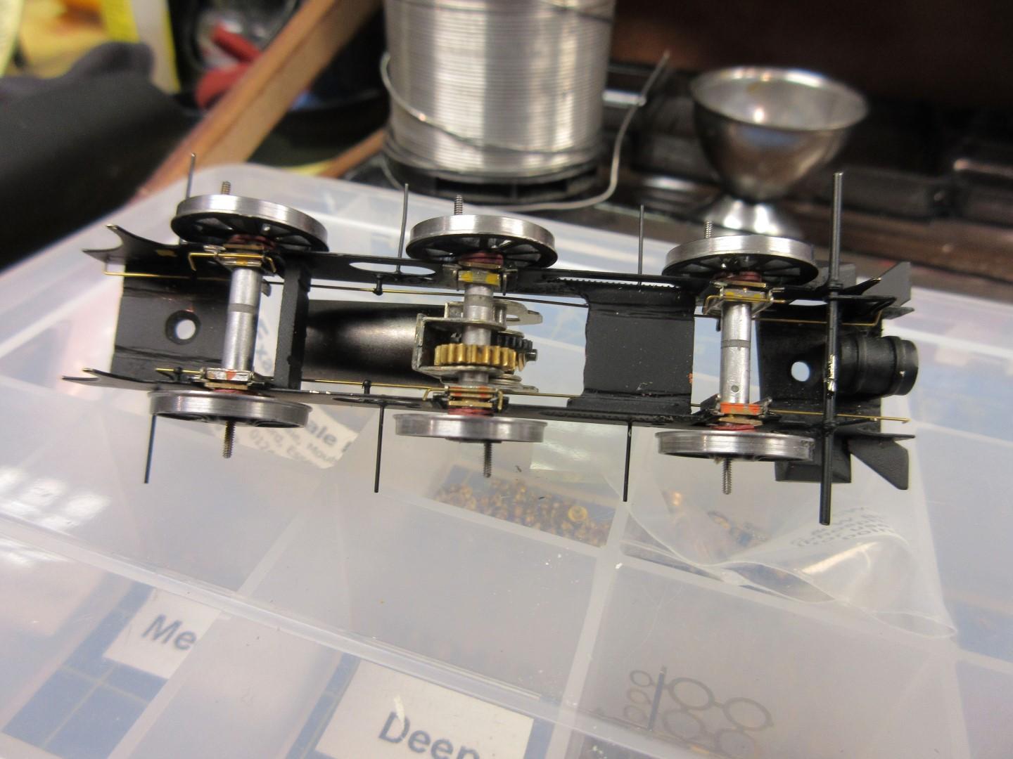
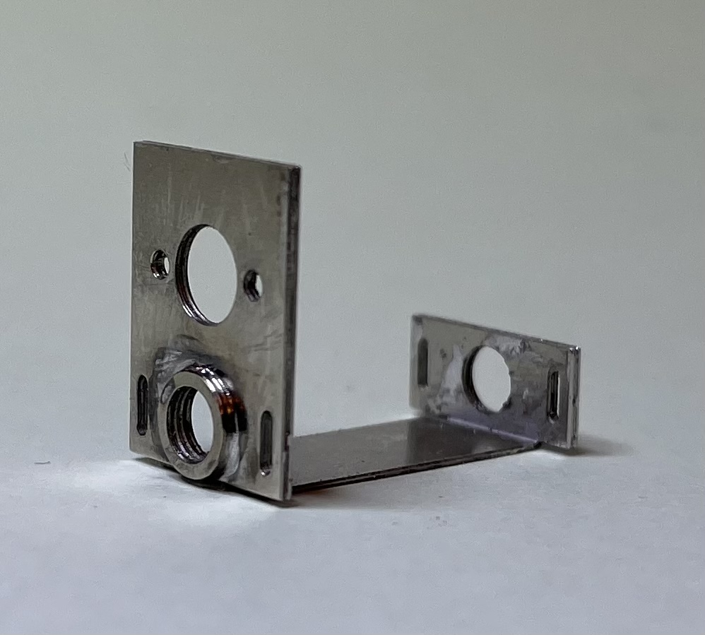
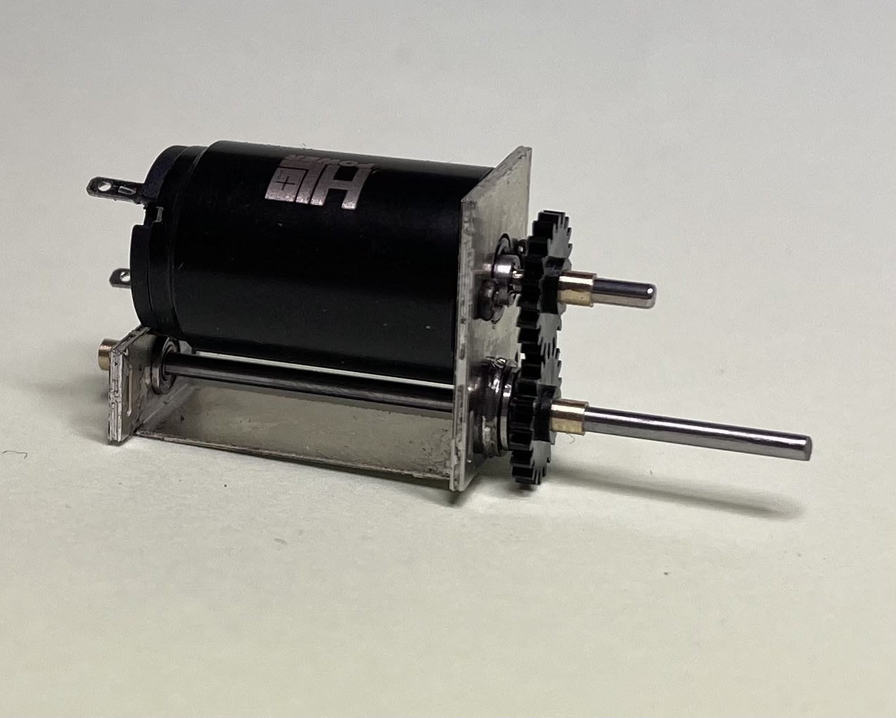
I have built several models to run on the Shipley MRS’s Clayton (EM) layout using such a drive system. The Clayton layout includes the 1:50 gradient on the embankment to the East of Clayton station and loco’s built conventionally have proven incapable of hauling prototype length trains up this gradient. I still have several more models to build for Clayton all requiring this type of drive system. I have therefore developed a standard unit for the drive system consisting of an etched foldup cradle on which to mount the motor and a drive shaft in the tender. The drive shaft is held in two miniature ball races and is situated below the level of the footplate. The 1320 coreless motor and the spur gears to drive the shaft are purchased from Chris at High Level Kits. The cradle is soldered between the inner frames of the tender and replaces one or more of the frame’s spacers as supplied in what ever kit I’m building at the time. This system allows the drive shaft to be located below the fall plate but this only works for locomotives with driving wheels of 5′ 8″ diameter or less. I have yet to come up with a gearbox design for locomotives with larger driving wheel diameters.
The other key aspects of my approach to chassis construction are CSB (continuous springy beam) suspension, and American pickups whereby the loco collects current from the nearside rail and the tender from the offside rail. By shorting the wheel rims to their axles it makes the chassis live and eliminates the need for any kind of wiper pickup. The gearbox in the locomotive uses the gears from a High Level Roadrunner+ gearbox but I etch my own gearbox frame so that I can incorporate miniature ball races for the input shaft. The system requires 2 universal joints (UJs). I use Neoprene tubing for the rear UJ as this does not need to flex by very much. The front UJ is a ball and socket unit obtained from Markit Models. This makes it relatively simple to separate the tender from the locomotive and the Neoprene tube prevents the drive shaft from plummeting to the ground.
I was provided with copies of original engineering drawings for the frames of the loco and tender as well as a number of reference photographs of the prototype. The drawings were imbedded and scaled in my CAD application (TurboCAD Delux) and the replacement chassis was designed in CAD by drawing up various components directly on top of the original drawings. Once the design work was complete the CAD file was sent to PPD Ltd who converted the drawing into a Nickel Silver etch. It was then just a matter of soldering up the frames much as I would any other etched kit.
There were some unexpected ‘challenges’ along the way. In particular, unlike the prototype, there was insufficient space behind the rear cylinder end plates for the front brake hangers. In order to fit them I had to resort to removing metal from the rear cylinder end plates behind the slide bars. The other major problem was the uneven distribution of ballast along the length of the loco’s superstructure. As a result the footplate had a 1mm height discrepancy front to back. The only way I could think to overcome this was to divide the CSB spring between the 2nd and 3rd driven axles so that the front two axles were sprung independently of the rear two axles. I could then use different thicknesses of CSB spring for the front and rear of the locomotive.
The one minor frustration with this approach is that it is only possible to test run the locomotive once the drive system has been installed in the tender. It is impractical to do this before the frames have been painted as the ball races and spur gears need to be Loctited in place. Last week the weather was sufficiently warm for me to spray the tender’s frames (in the garden shed) and I have therefore been able to install the motor etc. and test run the model for the first time. I’m delighted to report that there were no major problems and the model appears to be running okay light engine. I will be able to test run it on Clayton with a medium length train later this week, but I wont be able to test its full potential before the loco’s frames have been painted and the final assembly of the chassis has taken place as it is only then that the loco’s Ultrascale wheels will be permanently Loctited to their axles. Before then there is a risk the quartering of the wheels could fail under heavy load.
There is still some more detailing to add: sand pipes and inside valve gear will complete the chassis and then I need to make a replacement fall plate for the loco as the original is missing.
I the longer term the intention is to use this as the basis of a chassis kit for EM andP4 modellers wishing to convert the Bachmann ROD. Whilst the kit will include the components for the MIT drive system I will also include a bespoke gearbox frame to allow the motor to be installed in the firebox for those modellers not wanting to maximise the haulage potential of their locomotive.
I hope this has been of interest and if anyone has any questions about my M-I-T (motor in tender) drive system, or anything else, please feel free to ask.
Frank
-
April 25, 2023 at 8:30 am #244522
 Stuart FirthParticipant
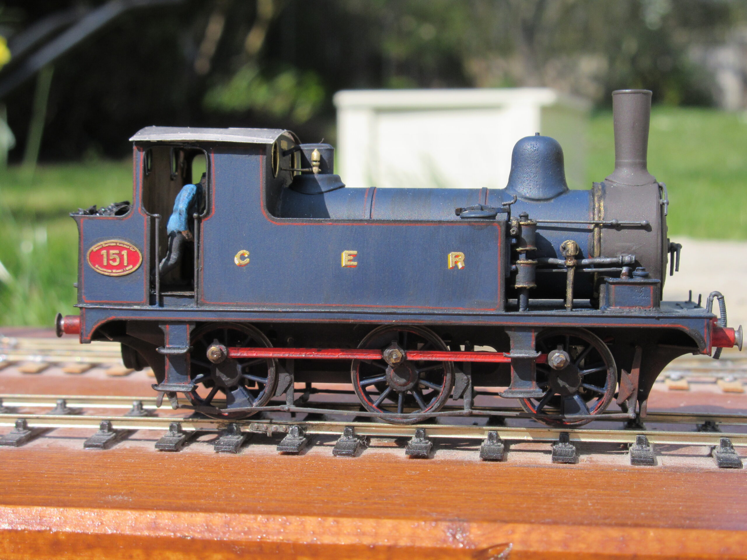
This looks amazing. Is that the loco. that Guy Williams described in MRJ? I think it was no. 63605, at least originally, and when I built a Pro-Scale one for a friend we gave it the same number as a tribute to him. Those High Level coreless motors must be incredibly powerful for their size? I am very tempted to try one but with mostly feedback controllers I am wary. I hope that one of the coreless settings on the Pentroller would suit them though.
-
April 25, 2023 at 9:36 am #244525Frank DaviesParticipant
Hi Stuart,
yes that is the same loco. The article was written in 1997 and appeared in edition 96 of the MRJ. Originally Guy built the model in its Robinson guise but subsequently rebuilt it in its Swindonised form for Pendon. I have a short video of it running on my test track which I tried to post yesterday but blew the size limit. I’m still getting to grips with posting to the Forum.
Frank
-
This reply was modified 1 year, 4 months ago by
 Frank Davies.
-
This reply was modified 1 year, 4 months ago by Frank Davies.
-
This reply was modified 1 year, 4 months ago by
-
April 25, 2023 at 3:42 pm #244534
 Paul TomlinsonParticipant
Interesting description and jolly nice videos – thanks for posting.
-
April 25, 2023 at 3:56 pm #244535Stuart FirthParticipant
I must admit that one of the things that puts me off using CSBs is getting the balance and overall weight right. The learned types on the S4 website are always saying the riding is so much smoother than compensated – what’s your feeling about this one now it’s running?
-
April 25, 2023 at 5:27 pm #244540Frank DaviesParticipant
Hi Stuart,
I would have to agree with the P4 boys you’ve spoken to that models fitted with springs appear to glide through any point work with a very satisfying clickety click as compared to the more clunky sound of a compensated chassis. Getting the balance right when building a CSB sprung model from scratch is relatively easy because you can play around with the ballast before finally installing it, but with the ROD the ballast was already a done deal so when I realised how far off level it was the only choice was to divide the springs front to back.
Next time you build an 0-6-0 I’d recommend you give CSB a go if you already use compensation.Frank
-
April 26, 2023 at 4:00 pm #244544Stuart FirthParticipant
Perhaps I’ll try it one of these days
-
May 2, 2023 at 10:27 pm #244733
Paul Willis
ParticipantFrank wrote:
I would have to agree with the P4 boys you’ve spoken to that models fitted with springs appear to glide through any point work with a very satisfying clickety click as compared to the more clunky sound of a compensated chassis. Getting the balance right when building a CSB sprung model from scratch is relatively easy because you can play around with the ballast before finally installing it, but with the ROD the ballast was already a done deal so when I realised how far off level it was the only choice was to divide the springs front to back.
Next time you build an 0-6-0 I’d recommend you give CSB a go if you already use compensation.Actually, you don’t even need to mess about with the ballasting to get the balance right. If you get the fixing points of the CSB pivots in the right place when you build the chassis, you should have it spot on. There is a spreadsheet on the CLAG website that allows you to input a couple of parameters and get all the answers out of it. Or they even have pre-defined “plots” for many common locomotives and wheelbases.
There’s also a long and extremely accessible topic by Will Lichfield on the Scalefour Forum that tells you all that you need to know (and a few things that you didn’t even realise) about springing using CSBs.
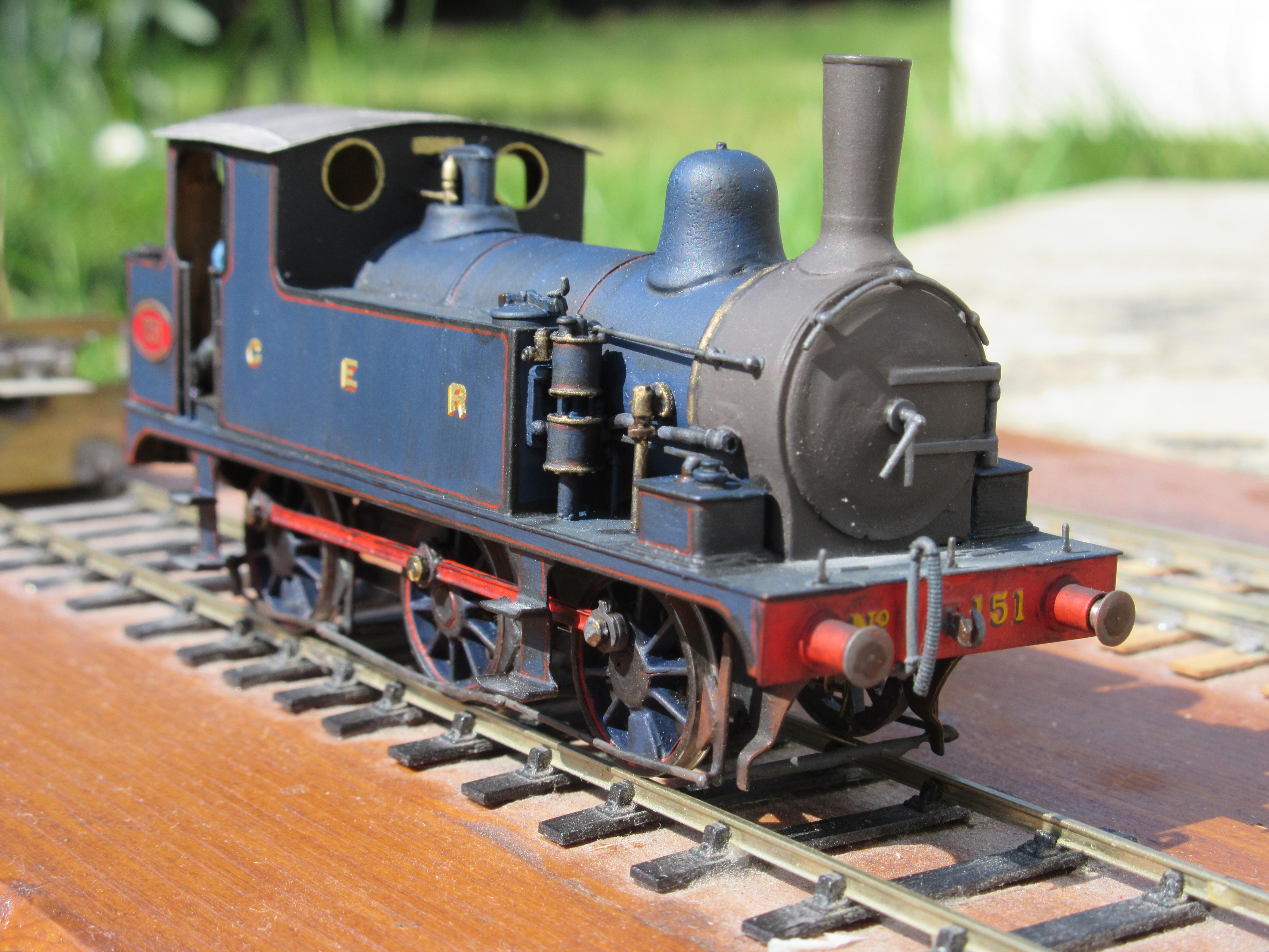
Suffice to say that given the improvement in smoothness and pick-up I’ve experienced, I’m completely sold on it. And it is just as easy to build a chassis using it as using compensation. Easier if you’re talking about eight-or ten-coupled!
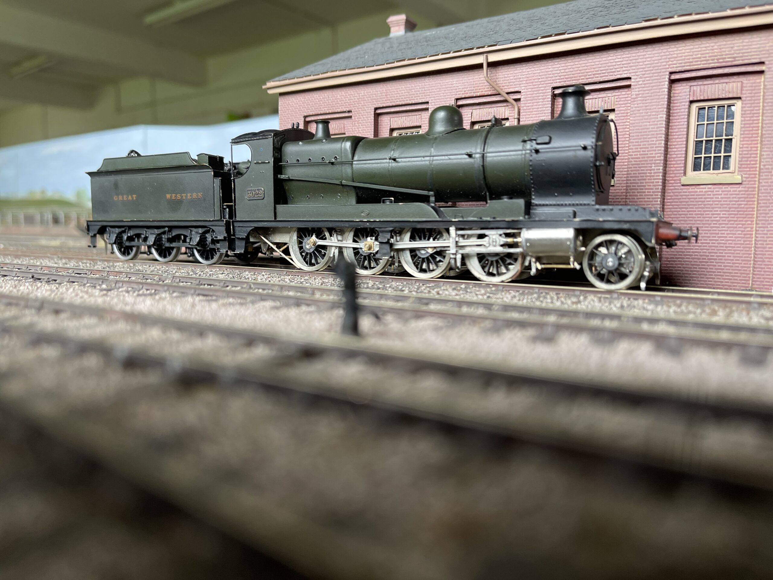
Here’s one of mine that I did earlier, part-built. A nice easy 0-6-0T, in the form of a GER E22 Buckjumper.
Best,
Paul
Attachments:
-
May 3, 2023 at 2:03 pm #244742Stuart FirthParticipant
Very nice. I tend to stick with what I know, if it works. However it really is time I did one with CSB as a comparison to all my compensated locos.
-
May 11, 2023 at 9:21 pm #244796Frank DaviesParticipant
A STEP TOO FAR?
I have now completed the build of the Pendon ROD’s chassis. Finishing off nearly went as planned although in the end I omitted the centre sand pipes because there was an insufficient gap between the brake hangers and coupling rods to accommodate them.
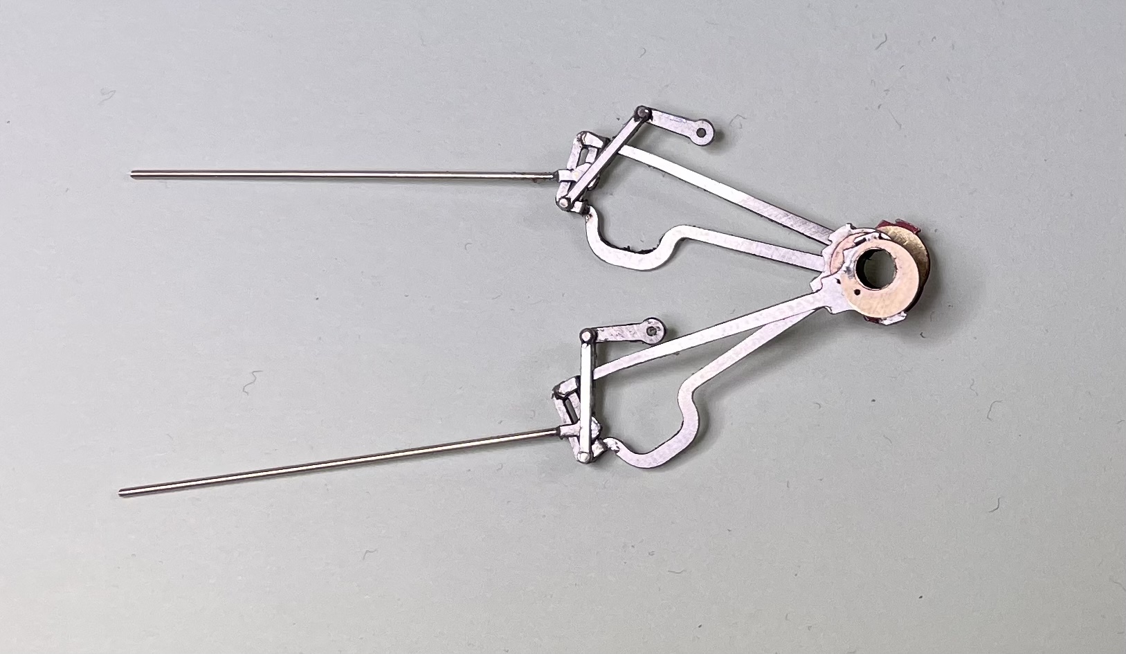
It was always my intention to make the valve gear operational, although if things hadn’t gone to plan I was quite prepared to solder it all up rigid. The eccentric sheaves were obtained from Brassmasters and were originally designed by Martin Finney for use in his Great Western locomotive kits. The rest of the valve gear components were designed using CAD and drawn over a scaled Work’s engineering drawing. Rather than mount the eccentric sheaves directly on the axle I chose to turn up a shouldered brass tube (1/8″ i/d) mounting the sheaves on this. The tube was then mounted on the axle using a 16BA bolt to lock them together. Removing the bolt allows the axle to be removed from the chassis, and in the event the valve gear build had not been successful the bolt could have been omitted and the eccentrics would then have become non-operational.
The attached video shows the valve gear in operation along with the entire MIT (motor in tender) drive system.
In reality, once the chassis is installed in the locomotive it is very difficult to see the valve gear, let alone observe it moving. And once it is operating on the Vale scene will anyone be able to see it? So was it a step too far? I’ve enjoyed the challenge so for me it doesn’t matter.
All that remains is to await delivery of replacement (Ultrascale) tender wheels. I will then strip the chassis down and clean it thoroughly before sending it off for painting and weathering. I can then undertake final assembly at which point the driving wheels will be permanently adhered to their axles. At the moment I am investigating what adhesive to use. Up until now I have always used Loctite 601 but I have recently been advised that Loctite doesn’t adhere particularly well to plastic. We still need to be able to remove the wheels from their axles in the event the chassis needs a major service so I’m going to have to experiment with various adhesives to ensure I find the most appropriate type for this and future chassis builds.
-
May 12, 2023 at 6:59 am #244800Participant
Morning Frank,
I can then undertake final assembly at which point the driving wheels will be permanently adhered to their axles. At the moment I am investigating what adhesive to use. Up until now I have always used Loctite 601 but I have recently been advised that Loctite doesn’t adhere particularly well to plastic. We still need to be able to remove the wheels from their axles in the event the chassis needs a major service so I’m going to have to experiment with various adhesives to ensure I find the most appropriate type for this and future chassis builds.
It’s clearly going to be late for this build, but one of the great advantages of the CSB method of chassis building is that you can just drop the driving wheels out without removing them from the axles or disturbing the quartering.
By removing the CSB wires that hold the axle bearings in their guides, the whole lot can just drop downwards. You may have a keeper plate under there as well, holding brake gear and/or pickups, and that can be removed as well.
The method gives a lot of flexibility for maintenance and adjustment, as well as ease of building.
As for glues, I’ve used Loctite 601 (or rather 603, which I understand has replaced it) for many years with plastic centred wheels, and no specific problems have been found. It is widely held as the best adhesive for this role. Yes, it can shift under excessive torque, but I haven’t heard of a modelling adhesive that won’t eventually. It works for me. The belt and braces solution is drilling and pinning the axle of course. However that has it’s own challenges, not least if disassembly is needed in the future.
All the best,
Paul
-
May 19, 2023 at 2:04 pm #245023
Iain Kirk
ParticipantA fascinating development, especially if you hope to build a number of ROD/O4s – bravo Frank…
-
-
AuthorPosts
- Only logged in EMGS members can reply to this topic