› Members Forum › Track › Scratch building track › Building Points – First Attempt
- This topic has 9 replies, 3 voices, and was last updated 1 year ago by
Duncan Forbes.
-
AuthorPosts
-
-
August 26, 2023 at 1:54 pm #245973
Duncan Forbes
ParticipantHello everyone.
I’m recently returned to model railways after many years and I’m having my first attempt at building points.
Ive seen lots of youtube videos and read the EMGS manual and have built myself a test point with the bits of rail, chair and sleepers i bought from EMGS for my attempt at building plain track. Building the point involved chopping the plastic chairs to fit, or missing them out completely. For the places where we would have the sliding chairs, or the bit under the ‘v’ i used some 0.6mm plasticard to keep the track level, and for the long spleepers i cut some 0.8mm plasticard into stips.
Apart from the plasticard sleepers which have gone a bit curly i am really pleased with what i’ve done particularly building and using a 1:6 v jig as descirbed in the manual. I also now know what wing rails are for!
Where i am struggling is the switch rails. I want a manual control (ideally using my fingers initially) and am attempting to create an over-centre spring mechanism. THese seem to be built from piano wire, which i dont currently have, so i have been attempting to ‘test’ the process using bits of wire i’ve got around including ordinary staples (of various sizes and stiffnes) which i have bent to shape.
Not necessarily suprisingly this isnt working too well. and i am struggling to get the points to lock on one side or the other. Also the swich rail tends to lift slightly when i have a spring in place.
<p style=”text-align: left;”>Piano wire doesnt seem to be sold in multi-diamemeter packs, and I wondered what diameter wire people would recommend for this technique, also how close together the two holes that hold the spring should be. Alternatively whether there is a better way to lock the point in place</p>
Below is a picture of my attempt. You can see the swich rail is lifting, and also that i’ve got the two holes farily close together. (also the tiebar is a bit a scrap pcb, and im not powering this test point)Any thoughts or help would be appreciated. Cheers Dunc
<p style=”text-align: left;”>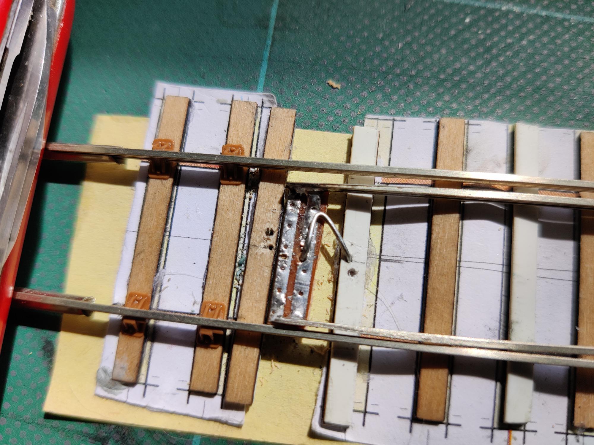 </p>
</p> -
August 26, 2023 at 8:29 pm #245977
 Paul TomlinsonParticipant
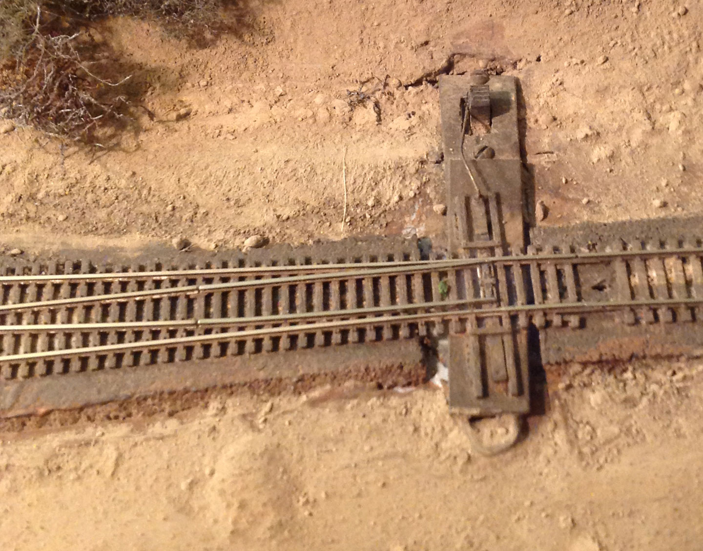
Duncan, Hello. I haven’t yet used one, but have you come across using a slide switch to control frog polarity, and, via a wire connection to the tiebar, move and hold the switch rails in position?
I’ve struggled to find a photo on the WWW, but here’s one, and a link to a Youtube video, I’d suggest skipping to about 10m40s to see if you think the idea is worth pursuing…
Attachments:
-
August 27, 2023 at 1:02 pm #245987Participant
THanks Paul. That is a really neat idea, and it deals with the frog polarity issue at the same time.
Checking on Amazon and RS Components it looks like you can get switch travel of between 1.5mm and 2.5mm which i’d have thought was idea.
One of the commenters in the youtube video noted that you needed to make sure that the switch you buy breaks contact with one wiper before making contact with the next or you will get short between the rails. Amazon components dont mention this, but a few of the datasheets on RS did note that it ‘broke’ before ‘making’
I’m definitely going to try this. In fact i’ve just found an old toy with a switch that i can scavenge…. Hopefully i can try that today or tomorrow… exciting!
Cheers Dunc
-
August 27, 2023 at 2:10 pm #245988Paul TomlinsonParticipant
Cheers, Dunc. BTW, If you use tiebar made from a strip of copper-clad/PCB which extends under both stock rails (perhaps disguised as a sleeper), this should stop the switch rails rising and causing problems.
All the best,
Paul
-
August 29, 2023 at 11:39 am #246002
 Stuart FirthParticipant
I must admit I have been dithering terribly on how to control the points on the little American HO layout I’m building, and this might be the best solution. If I bolt the switch to the underneath of the 9mm ply it will be more or less flush with the top and can be hidden under something quite easily.
-
August 29, 2023 at 4:04 pm #246006Participant
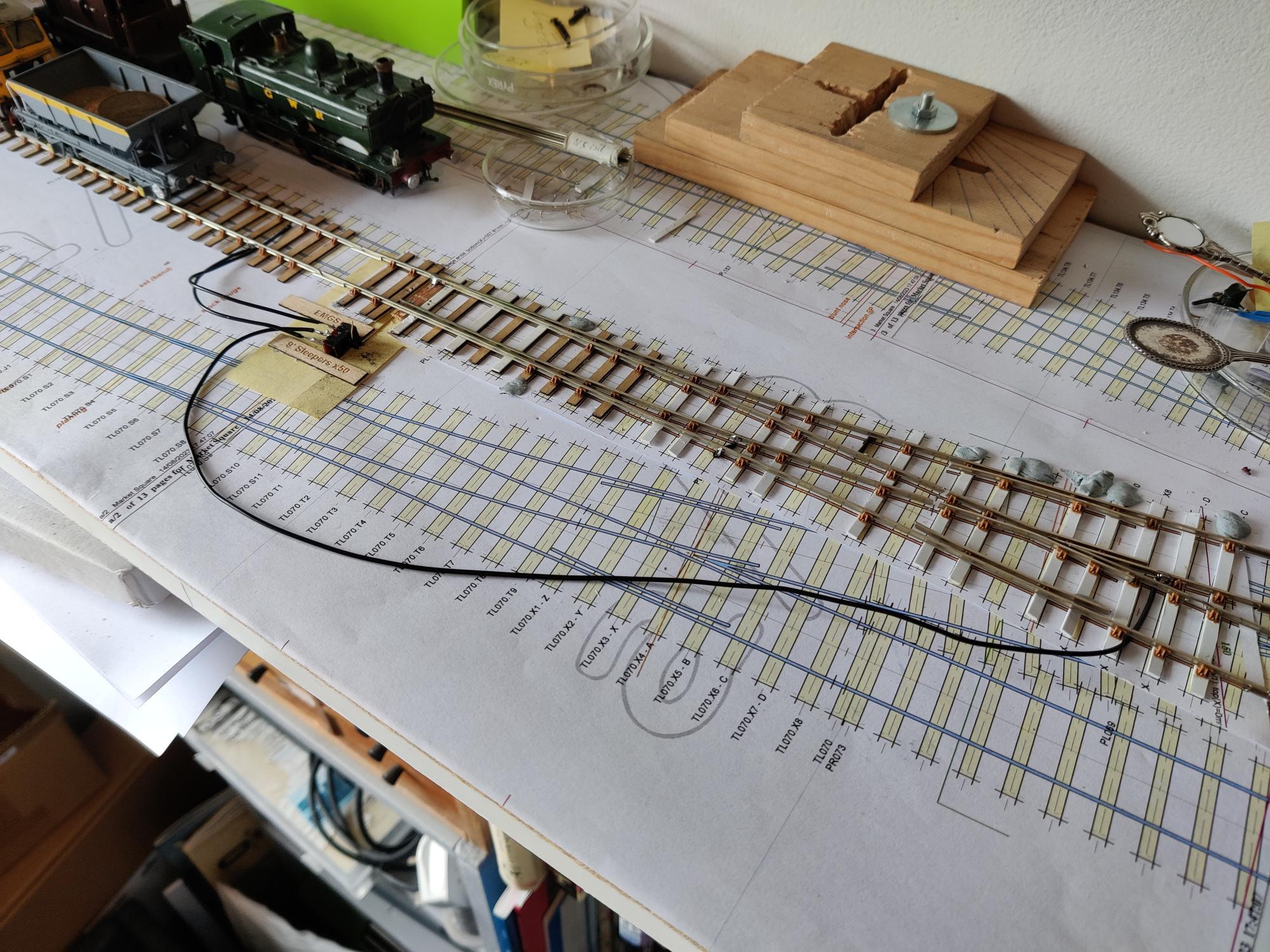
So…. I’ve added the slider switch as suggested by Paul to my turnout, and it works great. It locks the point in place and changes the polarity.
As you can see from the photo below i mounted the switch sideways to test it. Drilling a hole in the knob and connecting to the tie bar with 0.45mm wire. For the electrics i just connected the centre pin of the switch to the v and the outer pins to the rails.
I swapped the tiebar for a longer strip of PCB to provide room to drill a hole. As Paul says this does prevent the switch rail from rising.
I did get stumped for a while when i found i couldnt isolate a train on a section of track when the points were turned. I eventually found that there is a metal pin within the plastic slider switch which made a connection between: the rail, the tiebar, my control wire, the metal within the slider switch, the centre pin and the crossing v. Arrhhhhhhhh. To solve this i scraped back the Cu on the top of the tiebar. This had me flumoxed for ages, i just could not see how a circuit was being created!
Stuart, one thing i’ve noticed with my construction is that moving the electrical switch with my finger works well, but moving the switch blades directly works less well as the electrical switch is more ‘sticky’ and neither the switch nor the points latched. I suspect it would be better if the rails and switch are propoerly stuck down, and with a thicker (0.7mm?) wire. Everything in the picture is stuck down with Pritt or bluetac.
However i did see an alternative solution on youtube last night. See option2 in the link https://youtu.be/hjeNJiOFEgg?si=2dDzXXgyzvU3pBBW
This hides the switch under the base board, which might suit what you are looking do…
-
August 30, 2023 at 10:24 am #246018Stuart FirthParticipant
Hi Duncan – I’ve seen those blue TOU’s somewhere before. An under-baseboard TOU, based around a DPDT switch, operated by a brass rod from the edge of the baseboard was one of the options I looked at. There was also the hacked servo, I have built a prototype and it works well, but would obviously complicate the wiring. It really is this notion of the DPDT switch being right next to the point that appeals – it’s just so simple, and in the context of a very small switching layout, I think it might do the trick. The track on the San Francisco waterfront had just the same, with the switch levers recessed into the ground under a cover rather like a manhole cover – if I can solder an etched manhole cover over a length of square brass tube, that plugs on top of the DPDT switch, and slide it back and forth with my finger it would look right and be really simple to set up. Time to experiment!
-
August 30, 2023 at 11:18 am #246022Participant
Hi Stuart, yes it was the simpicity that i liked too. When i saw the video with the switch under the baseboard whilst it hid the switch it looked more complicated. For my first attempt i’m happy to have a partially submerged switch with the lever raised, but your comment about the man hole cover got me thinking and i’ve just googled and you can get dummy point motors from peco which might be attachable to the switch lever.
I’m very interested to know how you get on with your experiments
You say DPDT switches above. I was only planning to use SPDT switches, (3 terminal ON-ON), is there a reason for the DPDT, are you controlling a signal or is it a typo? Just curious…
Dunc
-
This reply was modified 1 year ago by
-
This reply was modified 1 year ago by
-
-
August 30, 2023 at 11:43 am #246026Stuart FirthParticipant
I’m not really sure why to be honest – My EM layout ‘Saltport’ uses DPDT switches at the baseboard edge, operating the points with wire-in-tube. Obviously I am only using one side of the DPDT so I’m not sure why I bought them!
Having said that there are one or two complicated bits where both sides of the switch have been used, to energise the crossings on a crossover adjacent to the point in question, which obviates the need for a separate switch, so I suppose it has come in handy. Where the DPDT comes into its own would be with hacked servos, where one side would change the polarity and the other operate the servo.
-
August 30, 2023 at 12:19 pm #246027Participant
Hee-Hee… I was only curious because i ordered the SPDT switches last night, and i thought i’d missed something significant… :). CLearly they give you greater flexibility, so ordering DPTP might have been sensible. Never mind they are pretty cheap and should be easy to swap over if i ever needed to..
-
-
-
AuthorPosts
- Only logged in EMGS members can reply to this topic