› Members Forum › Track › Point Operation › Droppers from point blades to TOU
- This topic has 6 replies, 3 voices, and was last updated 4 years ago by
Bob Allison.
-
AuthorPosts
-
-
May 22, 2022 at 10:07 pm #241662
David Mylchreest
ParticipantI’ve just finished my first point and I want to operate it from a TOU located under the layout. I’d be grateful for advice on how to make the wire droppers from the point blades to the TOU
Regards
-
May 29, 2022 at 3:38 pm #241684
Bob Allison
ParticipantTry following this link…
https://www.scalefour.org/forum/viewtopic.php?f=9&t=5707&p=76565&hilit=Tou#p76701
The awkward shape is only necessary if the dropper wires are used to stop the switch blades lifting upwards. If they are not, a simple “L” shape will do, with the short leg welded to the web of the blade.
You will find lots of other ideas if you search for “TOU” in the Scalefour Forum, which is open for reading only by non-members.
Regards,
Bob
-
This reply was modified 4 years, 1 month ago by
-
This reply was modified 4 years, 1 month ago by
-
May 30, 2022 at 11:57 am #241687Participant
Thanks for that Robert , most grateful
Regards
-
May 31, 2022 at 9:32 am #241692Participant
Of course, you can always solder the leg of the dropper to the switch blade. Oops!
-
June 2, 2022 at 12:21 pm #241698
Neil Docherty
ParticipantTried this approach using home made TOU; primary problem was stopping the dropper from flexing (initially had dropper going into a larger diameter tube that connected to TOU but subsequently just had dropper without intermediate tube) and not allowing to point to move all the way across. Increased movement on the TOU tended to then move point blade away from fixed rail. Increased dropper diameter (went to 1.5 mm diameter brass wire that did not flex)but then experienced problems with wheels just riding up where dropper wire soldered to point blade. Tried a number of different wire diameters and could not manage to either have no movement up and over or no flexing. Currently I have put the problem on the back burner where it is likely to stay for some time as accommodation recently changed and I don’t have the facility to solder outside (my wife does not like the smell). I feel the remedy may be to have the stiffest small diameter wire possible soldered to the point blades (possibly stainless steel or nickel silver) and then have them go into a tight fitting tube that connects to TOU. Please let us all know how you get on; some times I think that a lot of advice misses some of the niggly bits about getting things to work well.
-
June 4, 2022 at 9:43 pm #241709Participant
I’m currently using 1mm brass wire, simply because I’d run out of nickel silver which I’ve now ordered from Eileen.
The brass is probably not stiff enough but we’ll see.
Like you I’m using home made TOUs, mine are based in the Exactoscale model but are customised for my needs. I’ve used polystyrene sheet and strip and it works quite well.
-
-
June 5, 2022 at 5:04 pm #241712Participant
I have never really liked the twin dropper system: two holes instead of one and difficult to keep the switch blades a constant distance apart.
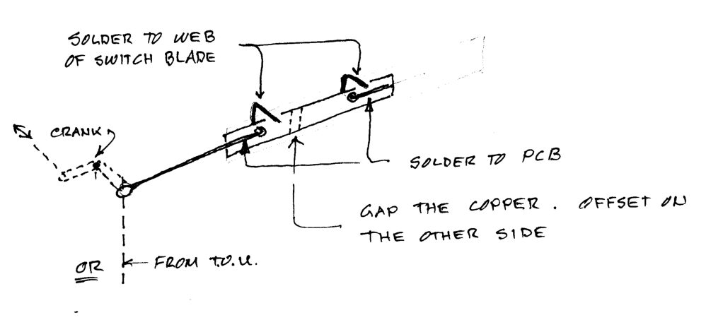
My preferred solution is based on Mike Norris’ on his Preston layout: a stretcher bar made out of thin pcb, bent wire passed through holes in the stretcher bar (about 16mm centres) with one end soldered to bar and the other end to the switch blade. Drive mechanism from below to taste – Mike uses a scale crank bar but a single wire from a TOU would work just as well.
Hopefully the sketch will clarify.
Attachments:
-
-
AuthorPosts
- Only logged in EMGS members can reply to this topic