› Members Forum › RTR Conversions › Locos › Quartering RTR wheels
- This topic has 5 replies, 3 voices, and was last updated 8 months ago by
 John Cutler.
-
AuthorPosts
-
-
February 12, 2022 at 10:10 am #240487
 John CutlerParticipant
I submitted a follow-up article on converting the Dapol B4 for the Newsletter and discovered I was writing a Manual Sheet (be warned!).
There are no replacement finescale wheels of the same appearance currently available so it is aesthetically preferable to re-use the Dapol wheels. Normally I would use a GW wheel-press to quarter drivers but the Dapol crankpins preclude its use (one could insert brass rod to fit tightly in the crankpin holes to use in the jig but I am not sure I would trust that; doubtless some readers have a usable technique; please enlighten!). John Simpson, the Manual editor, asked how to quarter these wheels, and I realise there is not much info around (what there is tends to be buried deep in other articles). Unfortunately space constraints precluded the use of my response in the B4 Manual Sheet. So for the benefit of novices and anyone else looking to quarter RTR wheels for the first time, here is my preferred method.
I use a Bill Bedford quartering jig, available from Eileens for £6.60 (soldering required): https://www.eileensemporium.com/materials-for-modellers/product/quartering-jig-4mm/category_pathway-1286
Note it is not available from Mousa Models. The attached photo shows the jig in use.
I have lined up the centres of the crankpin holes in the jig.They do not have to be at exactly 90 degrees. So long as they are the same for <i>all</i> axles, the quartering should work. You might prefer to use the jig with the crankpins in place; this means the quartering will not be at 90 degrees but will still work (unless any of the pins are of a different diameter). Note the mirror (ladies compact) is not strictly necessary but is extremely useful (and not just for quartering; I use it to check the passage of locos and rolling stock over my dodgy turnouts, for example).
After quartering, hold the wheels when screwing in the crankpins; otherwise the quartering may slip, especially if there are plastic bushes or axle inserts.I hope this of use.
If anyone has other thoughts or techniques for quartering, please contribute.
-
This topic was modified 4 years, 2 months ago by
 Steve Young.
Attachments:
-
This topic was modified 4 years, 2 months ago by
-
February 12, 2022 at 3:48 pm #240491
 Trade OfficerKeymaster
The method I have used in the past, before I got my hands on a GW wheel press, I got from, I think a Tony Wright video. It is a similar idea as the Bill Bedford jig but just eye balling it
Assuming you are mounting the wheels directly in the chassis:
Mount one wheel, then the second one at approximately 90 deg. Squint through one wheel and line up a spoke on that wheel with a spoke or gap (depending on odd or even spokes). Make up the second axle and put pace the coupling rod on the crankpins. check smoothness of running. Twist a wheel on the second axle slightly until smooth running is achieved. Continue with further axles in the same vein. A bit fiddly I admit and you have to be careful not twist the wheel of true.
Doesn’t work on solid wheels!
Of course if you want to be really pedantic you need to research which side is the leading side 😁 Now that is a debate that could trigger a few arguments
john
-
February 13, 2022 at 10:53 am #240520John CutlerParticipant
The eye-ball method is exactly the one I first used for the B4. However, tightly curved short spokes, an uneven number of spokes and a lot of solid wheel all conspire towards failure. The B4 failure was not complete but running was not smooth. Requartering using the Bill Bedford jig was a lot easier, especially in conjunction with the mirror, and improved the running considerably.
Having got so used to the GW wheel-press, I had almost forgotten about my old Bill Bedford jig. But it will now be my tool of choice for RTR wheels. Ultrascale do not like anyone using the GW press on their wheels and state its use invalidates their warranty. I am not sure why (does anyone know?) but I have some of their wheels that seem to have slipped on their axles so I will probably use the BB jig for them (no, I do not have the equipment or skill to pin them permanently in position afterwards). Unless someone has a better quartering technique?
Incidentally, for anyone worried about soldering up the jig, precision soldering is not required! So suitable for a novice or the cack-handed like me.
-
-
July 21, 2025 at 9:32 pm #252076John CutlerParticipant
Quartering Again
Having chosen to go down the route of using the Bill Bedford jig for quartering RTR wheels, I have discovered there are shortcomings:
1. All the wheels on a loco must be quartered using the Bedford jig. You cannot mix and match i.e. set one wheelset with the jig then use a GW press or eyeball to quarter the others. The jig does not set at precisely 90 degrees but will set all wheelsets consistently at the same angle.
2. The jig cannot work if there are bearings and spacing washers narrowly confined between a wheel and a final gear; the jig cannot support the axle at one end. This is the case with many RTR locos with offset final gear drives such as the Hornby Adams Radial.
I ended up resorting to using the eyeball method for the Adams Radial. It is impossible to use the GW wheel-press because the front driver crankpins are too long at 5mm (8mm gross). This loco is tricky to quarter for the human eye, even with a mirror, because the wheel has the crank at Pin Between spoke and there are 18 spokes. Too many of them and none at the desirable quarter points to give the eye an easy task when looking through the wheels.
A requirement for successful quartering is to ensure the axles are to the correct length beforehand. Measure the depth of the wheel (x2) and the required Back-to-Back to obtain this. Allow for any boss on the back of the wheel. Alan Gibson now require customers to cut/file their axles to length. If you do not do this, you will discover your GW wheel-press gives horrible results, and closure of the wheels in a vice fails. I use a mini-drill (with cutting attachments) or cheap diamond-coated files to reduce the axle lengths. Remember to lightly chamfer the ends of the axles afterwards so they will ease into the wheel holes and not cut into the plastic. I think AG chamfer them, so I only file back one end of an axle.
I have discovered a simple and fairly reliable eyeball solution using old tech! You need two pieces of Sellotape cut wider than the wheel diameter.
Fix one wheel on the axle permanently using a vice, taking care it is at 90 degrees. Add any gears, bearings and spacing washers.
With the crank at top dead centre, place the top of a piece of Sellotape horizontally across the full diameter of that wheel, so it crosses the centre of the axle, and stick it down. Turn this wheel with attached tape clockwise so it is at roughly 90 degrees vertically.
The next wheel should be added so that it has stiction i.e. be capable of being turned but not so loose it will fall off the axle; I reckon the axle needs to be about a quarter or a third of the way in.
Now add Sellotape to it. Turn this wheel so the crank is at top dead centre whilst keeping the opposite wheel with its tape in the vertical position. The Sellotape should indicate when both pieces are at 90 degrees. You can always use a protractor or engineer’s square to check. I find a mirror helpful, if only to check that the opposite tape has not moved out of position.
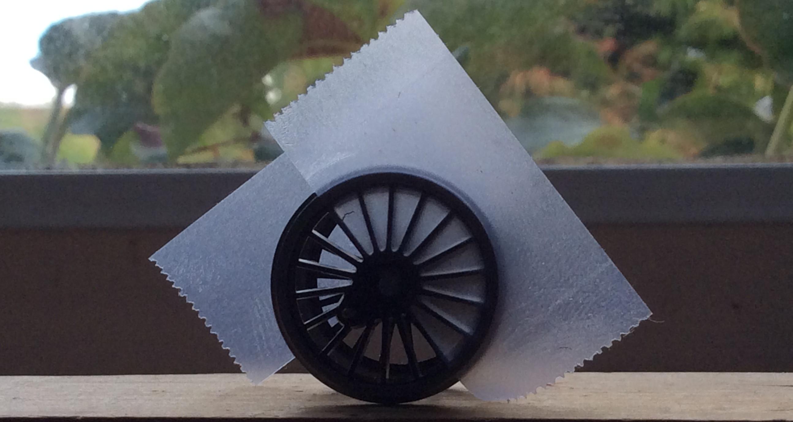
The spokes can still be seen through the Sellotape.
Once you are happy with the quartering, press the wheels together slightly to lock them and then in a small vice with a Back-to-Back gauge between them.
An alternative is to use Post-It Notes instead of Sellotape. These should be cut out of the sticky parts of the Notes to form two rectangles quite a bit wider than the wheel diameters. I recommend cutting these so the long sides are parallel; it is surprising how the eye/brain can be deceived if they are not. These give a more vivid indication of the quartering angle but are more likely to drop off or move position on the wheel; I prefer Sellotape.
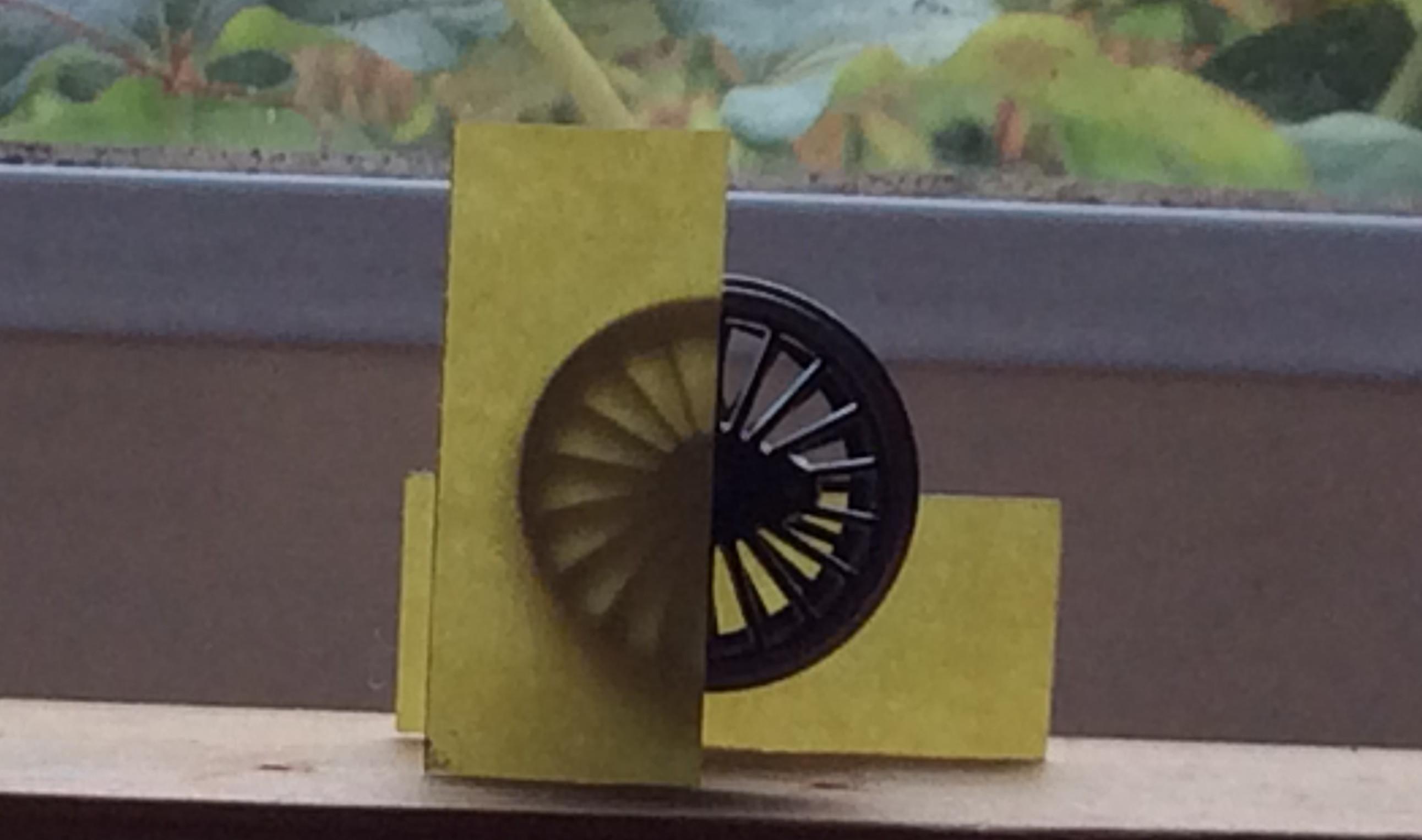
It is just coincidence that the Post-It Notes are supporting the wheel like this.
This method can also be used for those 3-cylinder locos where the cranks are not quartered but at 60 (?) degrees. It is also useful for older chassis where the wheels have to be quartered in situ i.e. the wheelsets do not drop in and there is no keeper plate.
I might retire both the GW wheel-press and the Bill Bedford jig!
-
August 15, 2025 at 4:48 pm #252264
 John HancockParticipant
John
not sure where we can get a Bill Bedford quartering jig from now that Eileens is gone
-
August 17, 2025 at 9:58 am #252271John CutlerParticipant
One of the cranks on the second N mogul I have converted apparently became loose. I discovered the cause was not the crank loosening but the crankpin rotating relative to the wheel! The result is the centre driver had to be dismantled and replaced. Ugh.
The remaining drivers had been quartered with a GW wheel press. This is not an option for the centre driver as the 8mm long crankpin is too long for the press to accept. So the only solution is to quarter by eye. After reducing the AG axle to length (22mm =16.7mm BB+ 5.1mm wheel widths + 0.2mm end protrusions), it was fixed with one wheel in a small vice. The other wheel is loosely fitted about 1mm into the axle at approximately 90 ̊. A piece of Sellotape is fitted along the along the line of the crankpin and the axle centre of this wheel to protrude beyond the tyre; this acts as a sighting marker so needs care. This is easy to place where a spoke is directly opposite the crankpin, as in this case. The fixed wheel needs to be set on the level with its crank at bottom dead centre. Then the loose wheel should be gently rotated so that the Sellotape is horizontal. A small mirror helps confirm all is level and square. Once happy, press the wheels together in the vice with a BB gauge in place.
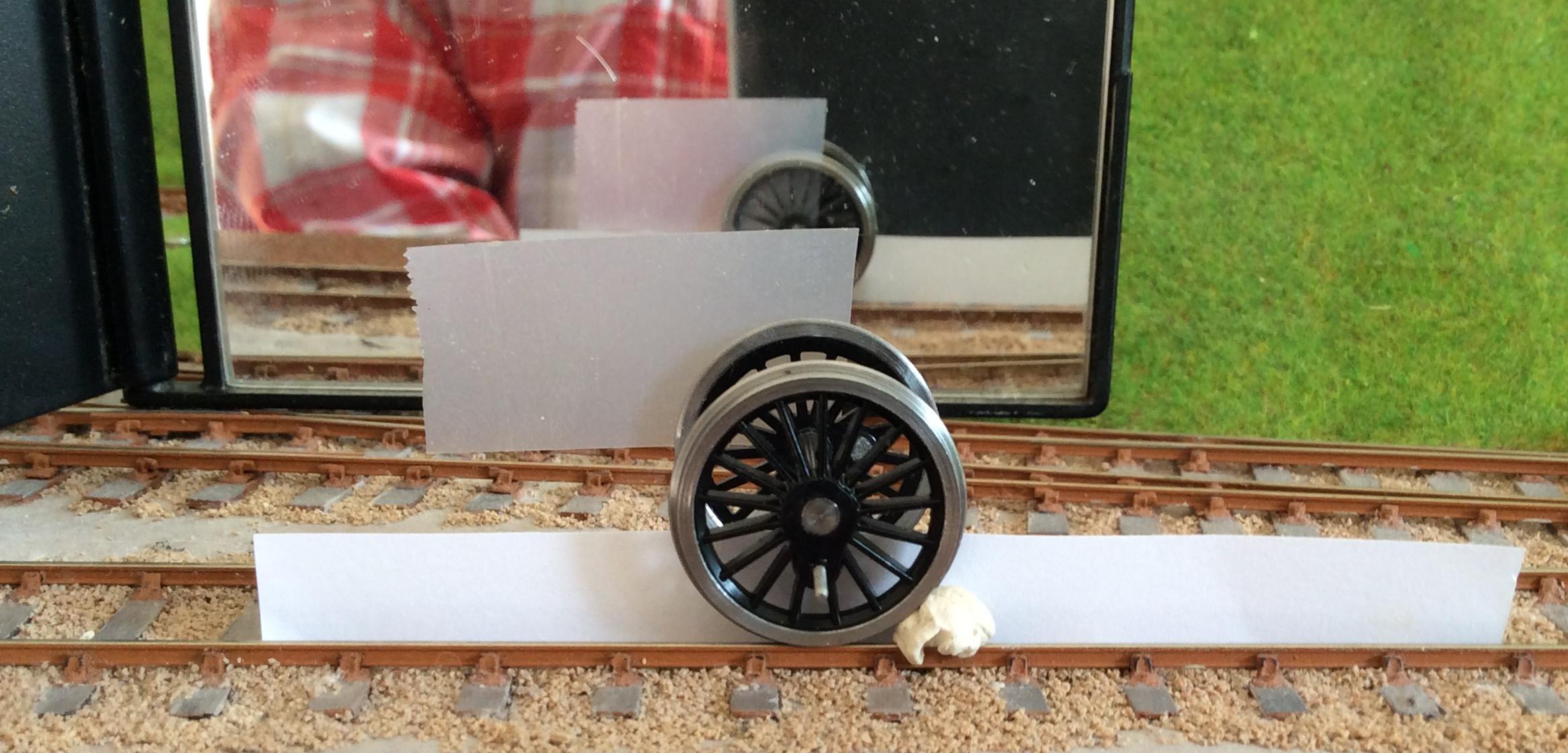
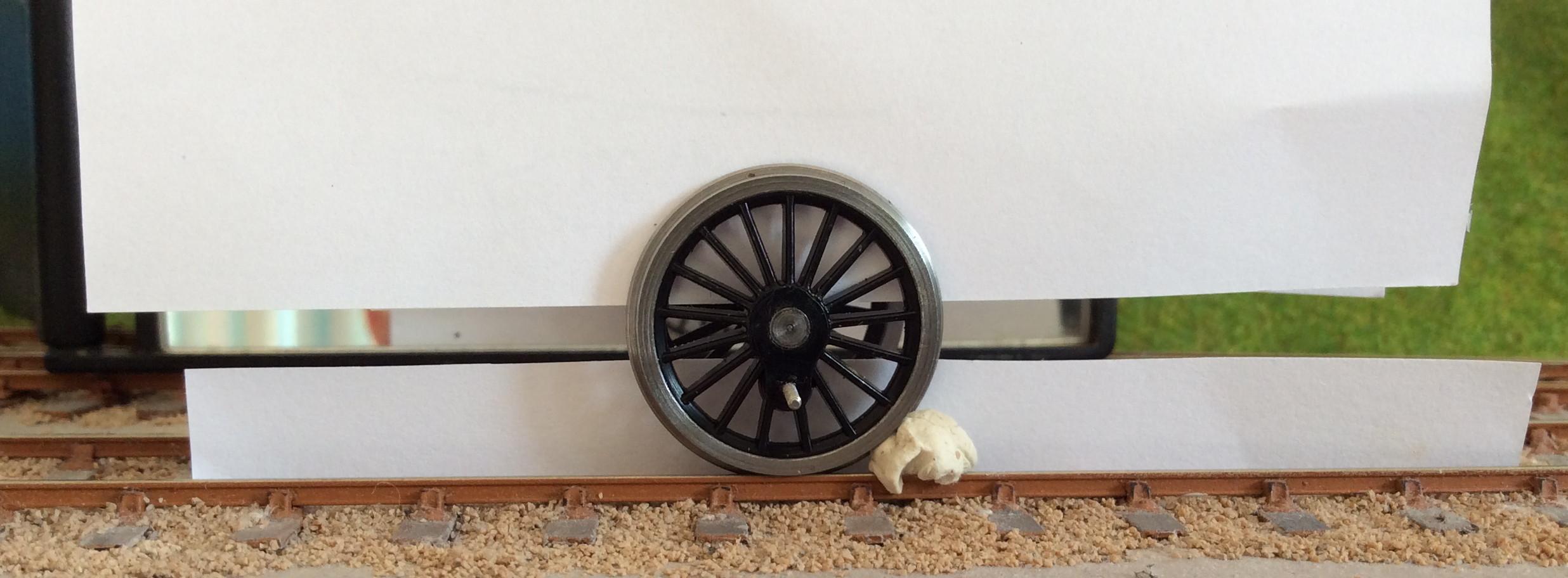
I found it surprisingly difficult to accurately position the fixed wheel at bottom dead centre. If there are spokes at 90 ̊ to the crankpin, then a piece of Sellotape across these can help the eye. This is not the case here. Fortunately there is a spoke opposite the crankpin, so setting this at vertical is the solution. Sighting this is confusing because of the spokes on the wheel behind, so a piece of white paper is used to temporarily blank these out of sight until the fixed wheel is in the required position.
-
-
AuthorPosts

- Only logged in EMGS members can reply to this topic